Skip to product information
1 of 11

PayPal, credit cards. Download editable-PDF and invoice in 1 second!

GB/T 1182-2018 English PDF (GBT1182-2018)

GB/T 1182-2018 English PDF (GBT1182-2018)

Regular price $1,500.00 USD
Regular price Sale price $1,500.00 USD
Sale Sold out
Shipping calculated at checkout.
Delivery: 3 seconds. Download true-PDF + Invoice.
Get QUOTATION in 1-minute: Click GB/T 1182-2018
Historical versions: GB/T 1182-2018
Preview True-PDF (Reload/Scroll if blank)

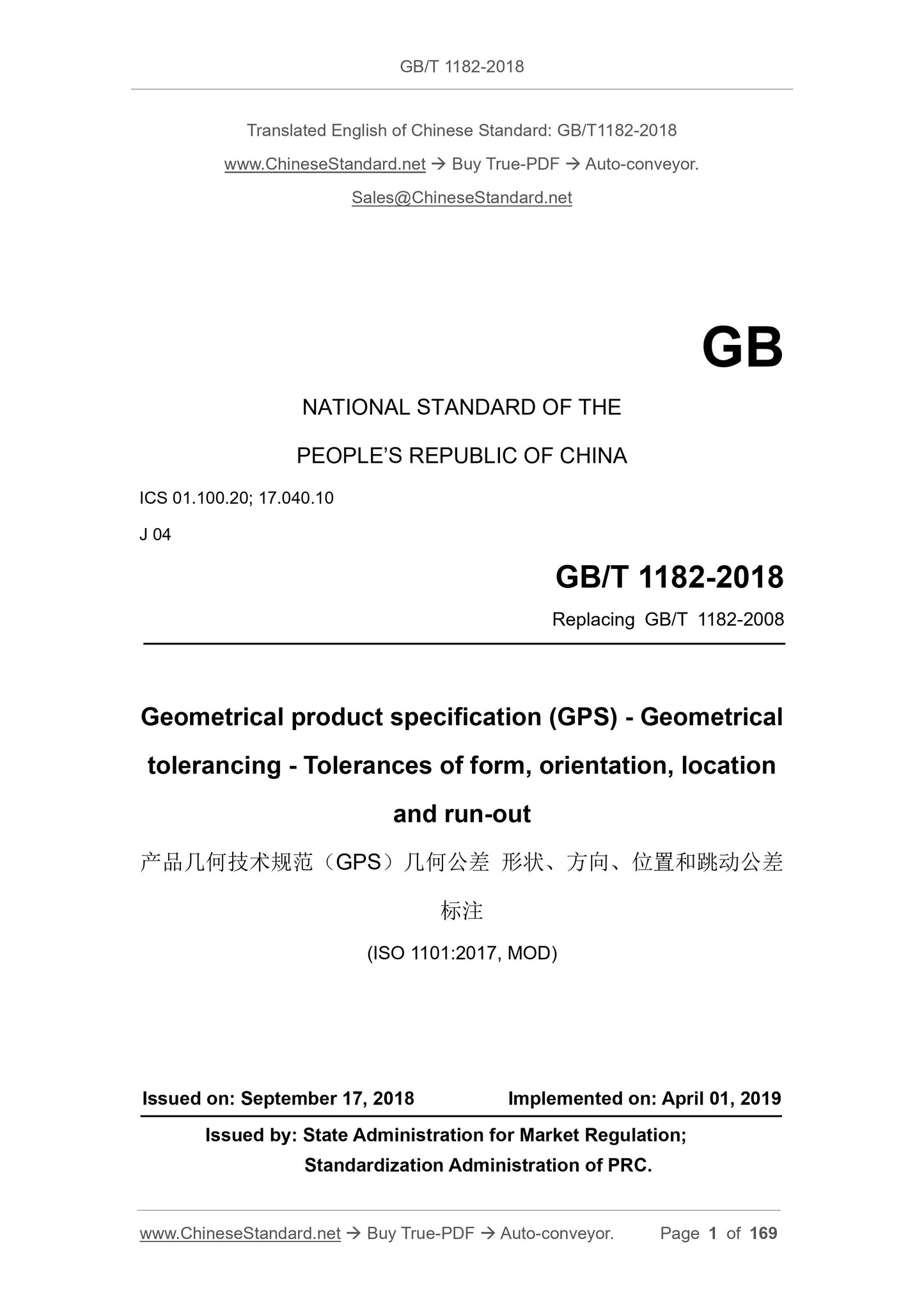
GB/T 1182-2018: Geometrical product specifications (GPS) -- Geometrical tolerancing -- Tolerances of form, orientation, location and run-out
GB/T 1182-2018
GB
NATIONAL STANDARD OF THE
PEOPLE’S REPUBLIC OF CHINA
ICS 01.100.20; 17.040.10
J 04
Replacing GB/T 1182-2008
Geometrical product specification (GPS) - Geometrical
tolerancing - Tolerances of form, orientation, location
and run-out
(ISO 1101:2017, MOD)
ISSUED ON: SEPTEMBER 17, 2018
IMPLEMENTED ON: APRIL 01, 2019
Issued by: State Administration for Market Regulation;
Standardization Administration of PRC.
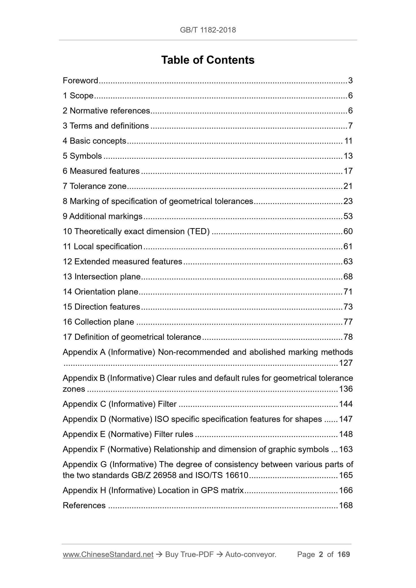
Table of Contents
Foreword ... 3 
1 Scope ... 6 
2 Normative references ... 6 
3 Terms and definitions ... 7 
4 Basic concepts ... 11 
5 Symbols ... 13 
6 Measured features ... 17 
7 Tolerance zone ... 21 
8 Marking of specification of geometrical tolerances ... 23 
9 Additional markings ... 53 
10 Theoretically exact dimension (TED) ... 60 
11 Local specification ... 61 
12 Extended measured features ... 63 
13 Intersection plane ... 68 
14 Orientation plane ... 71 
15 Direction features ... 73 
16 Collection plane ... 77 
17 Definition of geometrical tolerance ... 78 
Appendix A (Informative) Non-recommended and abolished marking methods
... 127 
Appendix B (Informative) Clear rules and default rules for geometrical tolerance
zones ... 136 
Appendix C (Informative) Filter ... 144 
Appendix D (Normative) ISO specific specification features for shapes ... 147 
Appendix E (Normative) Filter rules ... 148 
Appendix F (Normative) Relationship and dimension of graphic symbols ... 163 
Appendix G (Informative) The degree of consistency between various parts of
the two standards GB/Z 26958 and ISO/TS 16610 ... 165 
Appendix H (Informative) Location in GPS matrix ... 166 
References ... 168 
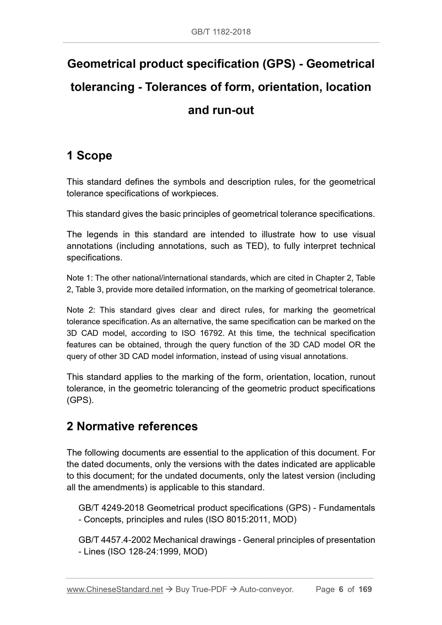
Geometrical product specification (GPS) - Geometrical
tolerancing - Tolerances of form, orientation, location
and run-out
1 Scope
This standard defines the symbols and description rules, for the geometrical
tolerance specifications of workpieces.
This standard gives the basic principles of geometrical tolerance specifications.
The legends in this standard are intended to illustrate how to use visual
annotations (including annotations, such as TED), to fully interpret technical
specifications.
Note 1: The other national/international standards, which are cited in Chapter 2, Table
2, Table 3, provide more detailed information, on the marking of geometrical tolerance.
Note 2: This standard gives clear and direct rules, for marking the geometrical
tolerance specification. As an alternative, the same specification can be marked on the
3D CAD model, according to ISO 16792. At this time, the technical specification
features can be obtained, through the query function of the 3D CAD model OR the
query of other 3D CAD model information, instead of using visual annotations.
This standard applies to the marking of the form, orientation, location, runout
tolerance, in the geometric tolerancing of the geometric product specifications
(GPS).
2 Normative references
The following documents are essential to the application of this document. For
the dated documents, only the versions with the dates indicated are applicable
to this document; for the undated documents, only the latest version (including
all the amendments) is applicable to this standard.
GB/T 4249-2018 Geometrical product specifications (GPS) - Fundamentals
- Concepts, principles and rules (ISO 8015:2011, MOD)
GB/T 4457.4-2002 Mechanical drawings - General principles of presentation
- Lines (ISO 128-24:1999, MOD)
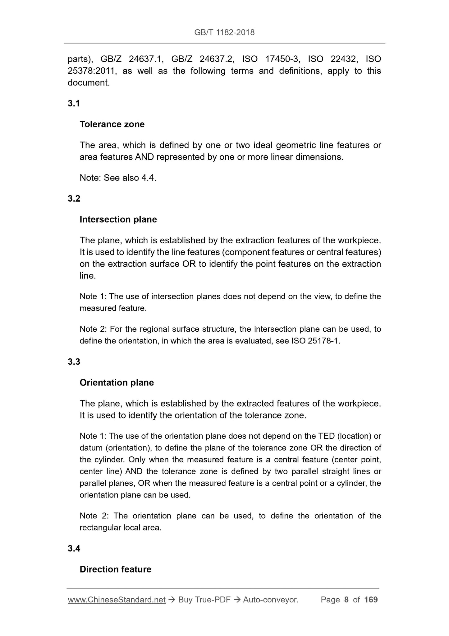
parts), GB/Z 24637.1, GB/Z 24637.2, ISO 17450-3, ISO 22432, ISO
25378:2011, as well as the following terms and definitions, apply to this
document.
3.1
Tolerance zone
The area, which is defined by one or two ideal geometric line features or
area features AND represented by one or more linear dimensions.
Note: See also 4.4.
3.2
Intersection plane
The plane, which is established by the extraction features of the workpiece.
It is used to identify the line features (component features or central features)
on the extraction surface OR to identify the point features on the extraction
line.
Note 1: The use of intersection planes does not depend on the view, to define the
measured feature.
Note 2: For the regional surface structure, the intersection plane can be used, to
define the orientation, in which the area is evaluated, see ISO 25178-1.
3.3
Orientation plane
The plane, which is established by the extracted features of the workpiece.
It is used to identify the orientation of the tolerance zone.
Note 1: The use of the orientation plane does not depend on the TED (location) or
datum (orientation), to define the plane of the tolerance zone OR the direction of
the cylinder. Only when the measured feature is a central feature (center point,
center line) AND the tolerance zone is defined by two parallel straight lines or
parallel planes, OR when the measured feature is a central point or a cylinder, the
orientation plane can be used.
Note 2: The orientation plane can be used, to define the orientation of the
rectangular local area.
3.4
Direction feature
The ideal features, which are established by the extracted features of the
workpiece. They are used to identify the width direction of the tolerance zone
(local deviation).
Note 1: The direction feature can be a plane, a cylindrical surface, or a conical
surface.
Note 2: The use of direction feature can change the width direction of the tolerance
zone, of the line feature, on the area feature.
Note 3: When the tolerance value is applied in the specified direction, rather than
the normal direction of the specified geometric form, it may use the direction feature.
Note 4: Direction features can be constructed, by the use of the datum, which is
marked in the second grid of the direction feature grid. The geometric form of the
measured feature can be used, to determine the geometric form of the direction
feature.
3.5
Compound continuous feature
A single feature, that is seamlessly combined by multiple single features.
Note 1: The compound continuous feature can be closed or non-closed.
Note 2: Non-closed compound continuous features can be defined by the "interval"
symbol (see 9.1.4) and the UF modifier (if applicable).
Note 3: The closed compound continuous features can be defined by the "full
circumference" symbol (see 9.1.2) and the UF modifier. At this time, it is a group
of single feature; the intersection with any plane, which is parallel to the collection
plane, forms a line feature or a point feature.
Note 4: The closed compound continuous features can be defined by the "full
surface" symbol (see 9.1.2) and the UF modifier.
3.6
Collection plane
The plane, which is established by the features on the workpiece. It is used
to define a closed compound continuous features.
Note: When using the "full circumference" symbol, always use the collection plane.
3.7
Theoretically exact dimension
TED
In GPS operation, the linear or angular size, which is used to define the
theoretically exact geometric form, range, location, orientation of the
features.
Note 1: The term "theoretically exact dimension" is abbreviated as TED, in this
standard.
Note 2: TED definition can be used:
- Nominal shape and size of the feature;
- Theoretical exact feature (TEF);
- The local location and size of the feature, including the local measured feature;
-Th...
View full details