1
/
of
6
www.ChineseStandard.us -- Field Test Asia Pte. Ltd.
GB/T 11024.4-2019 English PDF (GB/T11024.4-2019)
GB/T 11024.4-2019 English PDF (GB/T11024.4-2019)
Regular price
$140.00
Regular price
Sale price
$140.00
Unit price
/
per
Shipping calculated at checkout.
Couldn't load pickup availability
GB/T 11024.4-2019: Shunt capacitors for a.c. power systems having a rated voltage above 1 000 V -- Part 4: Internal fuses
Delivery: 9 seconds. Download (and Email) true-PDF + Invoice.Get Quotation: Click GB/T 11024.4-2019 (Self-service in 1-minute)
Newer / historical versions: GB/T 11024.4-2019
Preview True-PDF
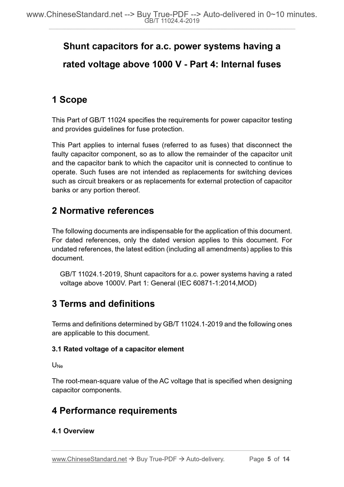
Scope
This Part of GB/T 11024 specifies the requirements for power capacitor testingand provides guidelines for fuse protection.
This Part applies to internal fuses (referred to as fuses) that disconnect the
faulty capacitor component, so as to allow the remainder of the capacitor unit
and the capacitor bank to which the capacitor unit is connected to continue to
operate. Such fuses are not intended as replacements for switching devices
such as circuit breakers or as replacements for external protection of capacitor
banks or any portion thereof.
Basic Data
| Standard ID | GB/T 11024.4-2019 (GB/T11024.4-2019) |
| Description (Translated English) | Shunt capacitors for a.c. power systems having a rated voltage above 1 000 V -- Part 4: Internal fuses |
| Sector / Industry | National Standard (Recommended) |
| Classification of Chinese Standard | K42 |
| Classification of International Standard | 31.060.70 |
| Word Count Estimation | 10,176 |
| Date of Issue | 2019-03-25 |
| Date of Implementation | 2019-10-01 |
| Issuing agency(ies) | State Administration for Market Regulation, China National Standardization Administration |
Share