1
/
of
12
www.ChineseStandard.us -- Field Test Asia Pte. Ltd.
GB/T 10485-2025 English PDF (GB/T10485-2025)
Regular price
$650.00
Regular price
Sale price
$650.00
Unit price
/
per
Shipping calculated at checkout.
Couldn't load pickup availability
GB/T 10485-2025: Road vehicles - Lighting and light-signalling devices - Environmental endurance
Delivery: 9 seconds. Download (and Email) true-PDF + Invoice.
Get Quotation: Click GB/T 10485-2025 (Self-service in 1-minute)
Newer / historical versions: GB/T 10485-2025
Preview True-PDF (Reload/Scroll-down if blank)
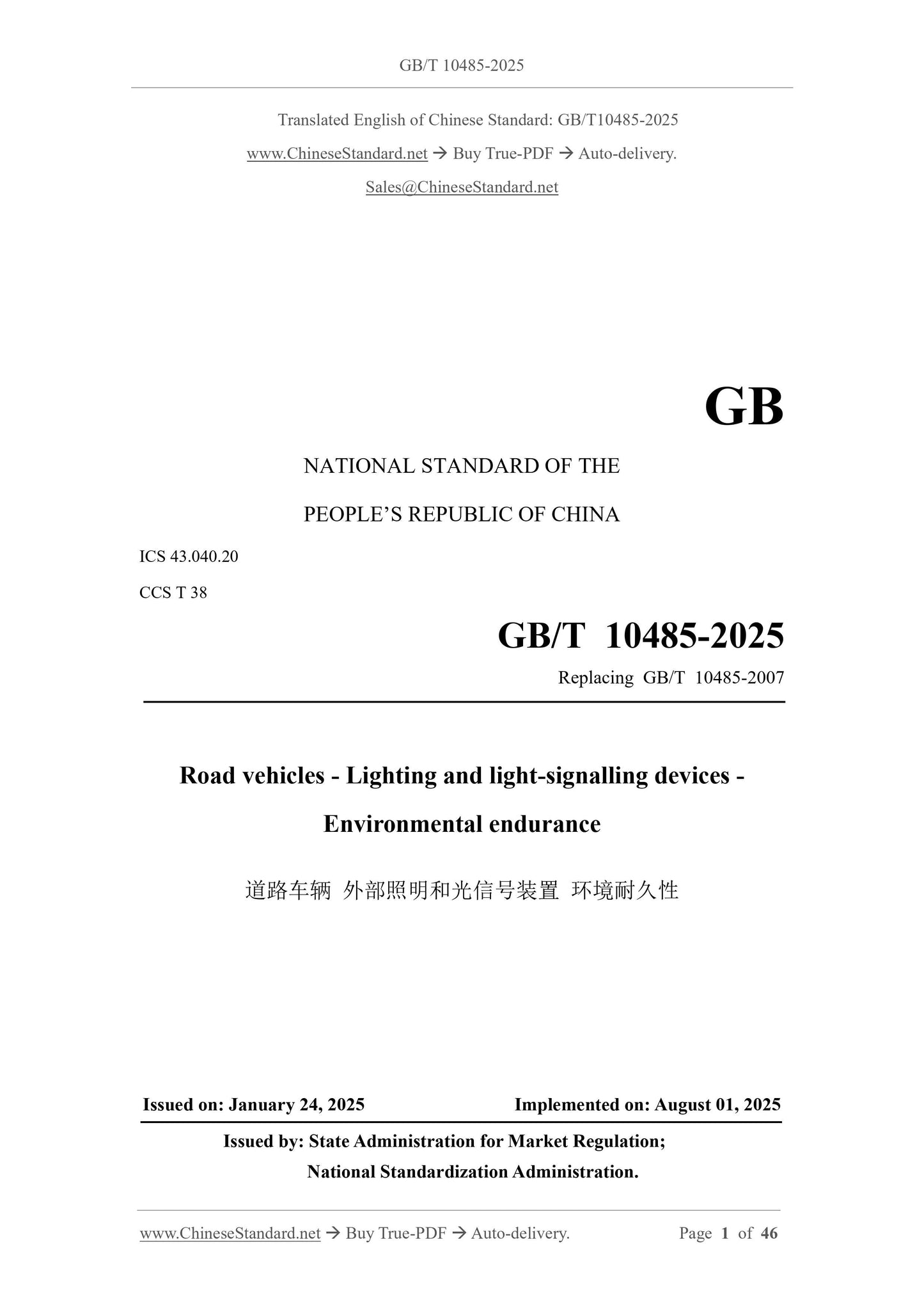
GB/T 10485-2025
GB
NATIONAL STANDARD OF THE
PEOPLE’S REPUBLIC OF CHINA
ICS 43.040.20
CCS T 38
Replacing GB/T 10485-2007
Road vehicles - Lighting and light-signalling devices -
Environmental endurance
ISSUED ON. JANUARY 24, 2025
IMPLEMENTED ON. AUGUST 01, 2025
Issued by. State Administration for Market Regulation;
National Standardization Administration.
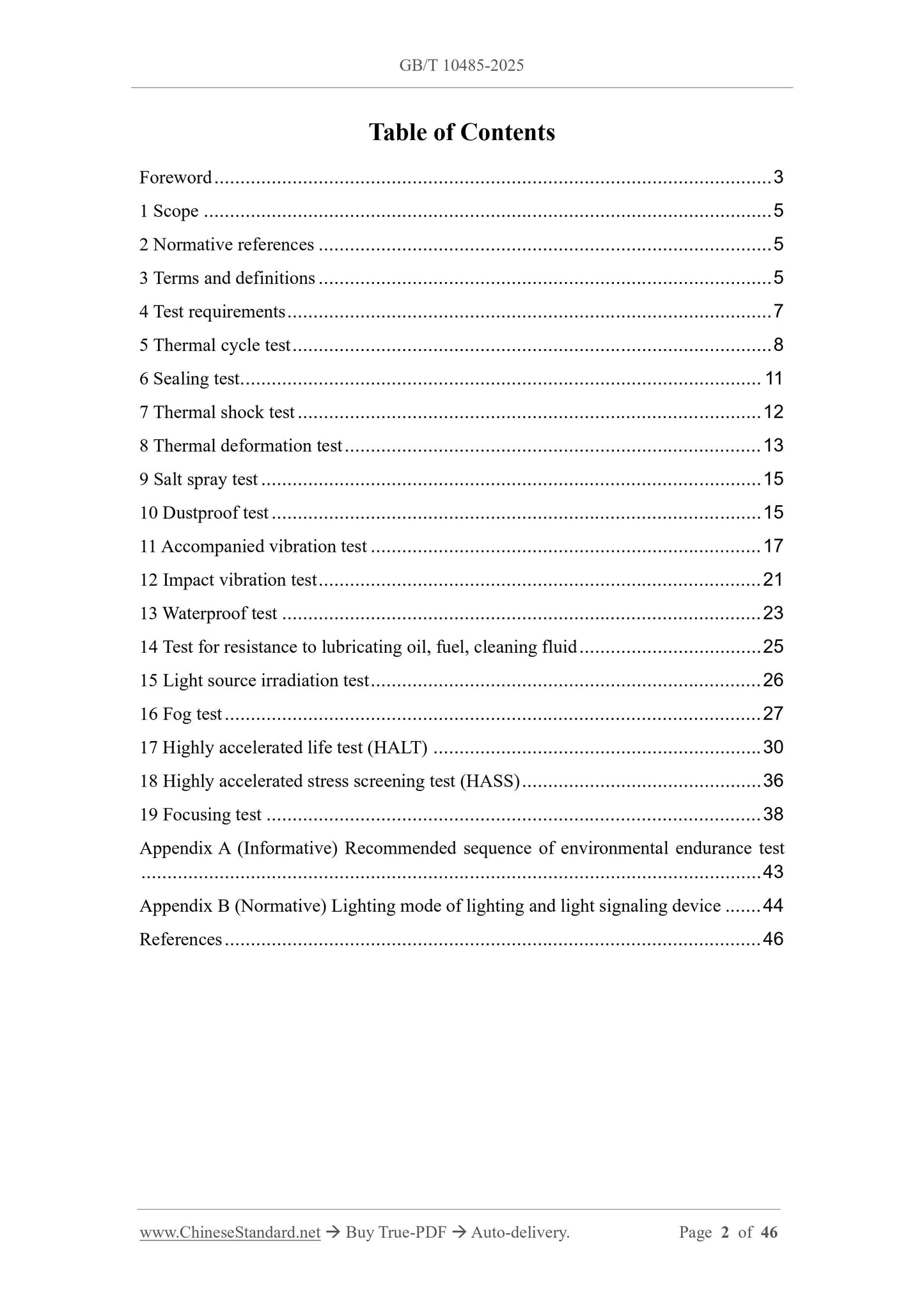
Table of Contents
Foreword... 3
1 Scope... 5
2 Normative references... 5
3 Terms and definitions... 5
4 Test requirements... 7
5 Thermal cycle test... 8
6 Sealing test... 11
7 Thermal shock test... 12
8 Thermal deformation test... 13
9 Salt spray test... 15
10 Dustproof test... 15
11 Accompanied vibration test... 17
12 Impact vibration test... 21
13 Waterproof test... 23
14 Test for resistance to lubricating oil, fuel, cleaning fluid... 25
15 Light source irradiation test... 26
16 Fog test... 27
17 Highly accelerated life test (HALT)... 30
18 Highly accelerated stress screening test (HASS)... 36
19 Focusing test... 38
Appendix A (Informative) Recommended sequence of environmental endurance test
... 43
Appendix B (Normative) Lighting mode of lighting and light signaling device... 44
References... 46
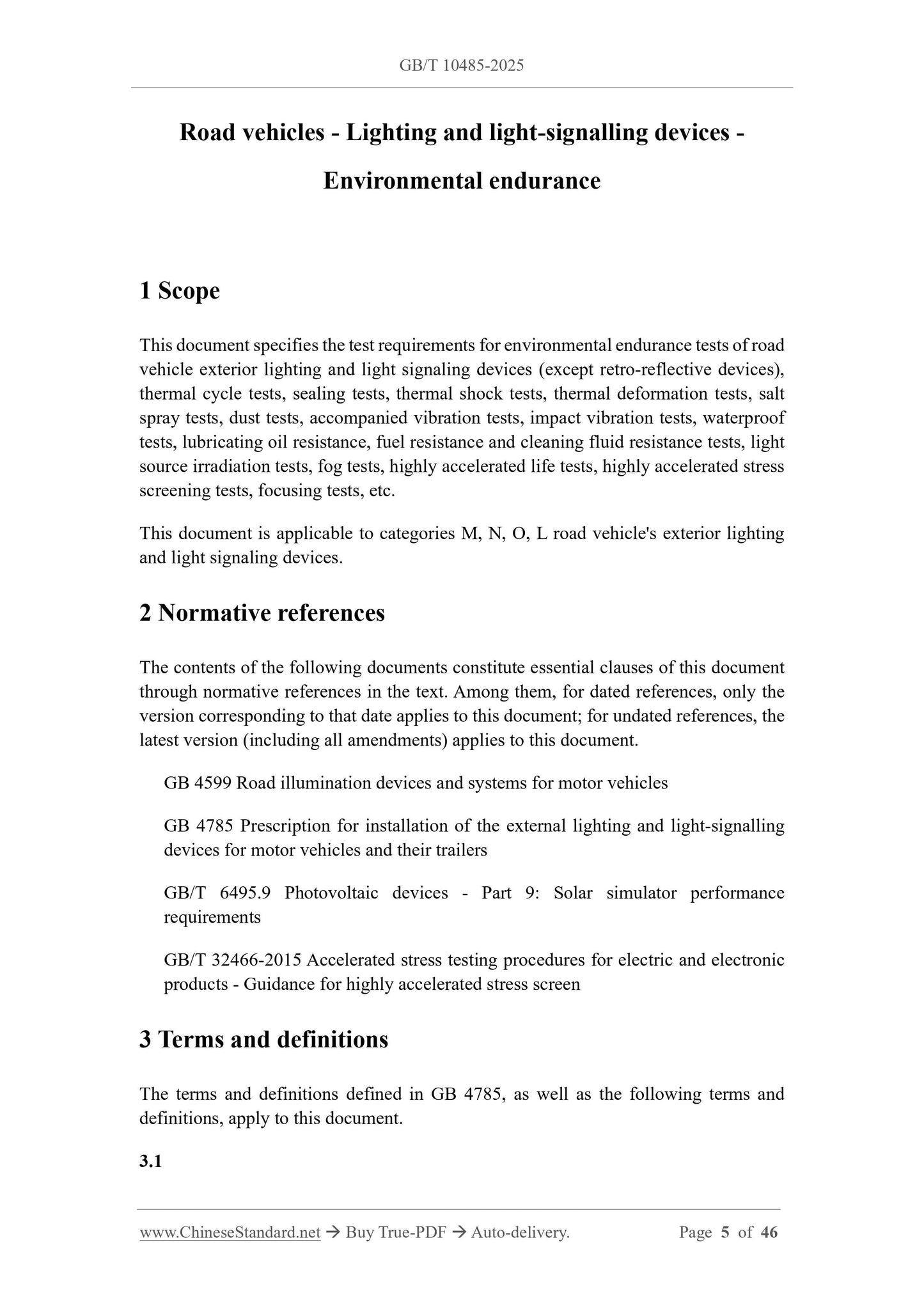
Road vehicles - Lighting and light-signalling devices -
Environmental endurance
1 Scope
This document specifies the test requirements for environmental endurance tests of road
vehicle exterior lighting and light signaling devices (except retro-reflective devices),
thermal cycle tests, sealing tests, thermal shock tests, thermal deformation tests, salt
spray tests, dust tests, accompanied vibration tests, impact vibration tests, waterproof
tests, lubricating oil resistance, fuel resistance and cleaning fluid resistance tests, light
source irradiation tests, fog tests, highly accelerated life tests, highly accelerated stress
screening tests, focusing tests, etc.
This document is applicable to categories M, N, O, L road vehicle's exterior lighting
and light signaling devices.
2 Normative references
The contents of the following documents constitute essential clauses of this document
through normative references in the text. Among them, for dated references, only the
version corresponding to that date applies to this document; for undated references, the
latest version (including all amendments) applies to this document.
GB 4599 Road illumination devices and systems for motor vehicles
GB 4785 Prescription for installation of the external lighting and light-signalling
devices for motor vehicles and their trailers
GB/T 6495.9 Photovoltaic devices - Part 9.Solar simulator performance
requirements
GB/T 32466-2015 Accelerated stress testing procedures for electric and electronic
products - Guidance for highly accelerated stress screen
3 Terms and definitions
The terms and definitions defined in GB 4785, as well as the following terms and
definitions, apply to this document.
3.1
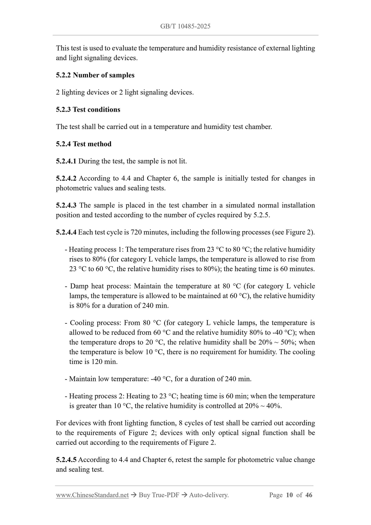
This test is used to evaluate the temperature and humidity resistance of external lighting
and light signaling devices.
5.2.2 Number of samples
2 lighting devices or 2 light signaling devices.
5.2.3 Test conditions
The test shall be carried out in a temperature and humidity test chamber.
5.2.4 Test method
5.2.4.1 During the test, the sample is not lit.
5.2.4.2 According to 4.4 and Chapter 6, the sample is initially tested for changes in
photometric values and sealing tests.
5.2.4.3 The sample is placed in the test chamber in a simulated normal installation
position and tested according to the number of cycles required by 5.2.5.
5.2.4.4 Each test cycle is 720 minutes, including the following processes (see Figure 2).
- Heating process 1.The temperature rises from 23 °C to 80 °C; the relative humidity
rises to 80% (for category L vehicle lamps, the temperature is allowed to rise from
23 °C to 60 °C, the relative humidity rises to 80%); the heating time is 60 minutes.
- Damp heat process. Maintain the temperature at 80 °C (for category L vehicle
lamps, the temperature is allowed to be maintained at 60 °C), the relative humidity
is 80% for a duration of 240 min.
- Cooling process. From 80 °C (for category L vehicle lamps, the temperature is
allowed to be reduced from 60 °C and the relative humidity 80% to -40 °C); when
the temperature drops to 20 °C, the relative humidity shall be 20% ~ 50%; when
the temperature is below 10 °C, there is no requirement for humidity. The cooling
time is 120 min.
- Maintain low temperature. -40 °C, for a duration of 240 min.
- Heating process 2.Heating to 23 °C; heating time is 60 min; when the temperature
is greater than 10 °C, the relative humidity is controlled at 20% ~ 40%.
For devices with front lighting function, 8 cycles of test shall be carried out according
to the requirements of Figure 2; devices with only optical signal function shall be
carried out according to the requirements of Figure 2.
5.2.4.5 According to 4.4 and Chapter 6, retest the sample for photometric value change
and sealing test.
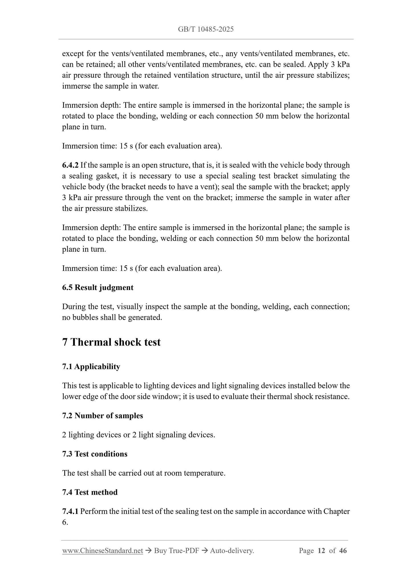
except for the vents/ventilated membranes, etc., any vents/ventilated membranes, etc.
can be retained; all other vents/ventilated membranes, etc. can be sealed. Apply 3 kPa
air pressure through the retained ventilation structure, until the air pressure stabilizes;
immerse the sample in water.
Immersion depth. The entire sample is immersed in the horizontal plane; the sample is
rotated to place the bonding, welding or each connection 50 mm below the horizontal
plane in turn.
Immersion time. 15 s (for each evaluation area).
6.4.2 If the sample is an open structure, that is, it is sealed with the vehicle body through
a sealing gasket, it is necessary to use a special sealing test bracket simulating the
vehicle body (the bracket needs to have a vent); seal the sample with the bracket; apply
3 kPa air pressure through the vent on the bracket; immerse the sample in water after
the air pressure stabilizes.
Immersion depth. The entire sample is immersed in the horizontal plane; the sample is
rotated to place the bonding, welding or each connection 50 mm below the horizontal
plane in turn.
Immersion time. 15 s (for each evaluation area).
6.5 Result judgment
During the test, visually inspect the sample at the bonding, welding, each connection;
no bubbles shall be generated.
7 Thermal shock test
7.1 Applicability
This test is applicable to lighting devices and light signaling devices installed below the
lower edge of the door side window; it is used to evaluate their thermal shock resistance.
7.2 Number of samples
2 lighting devices or 2 light signaling devices.
7.3 Test conditions
The test shall be carried out at room temperature.
7.4 Test method
7.4.1 Perform the initial test of the sealing test on the sample in accordance with Chapter
6.
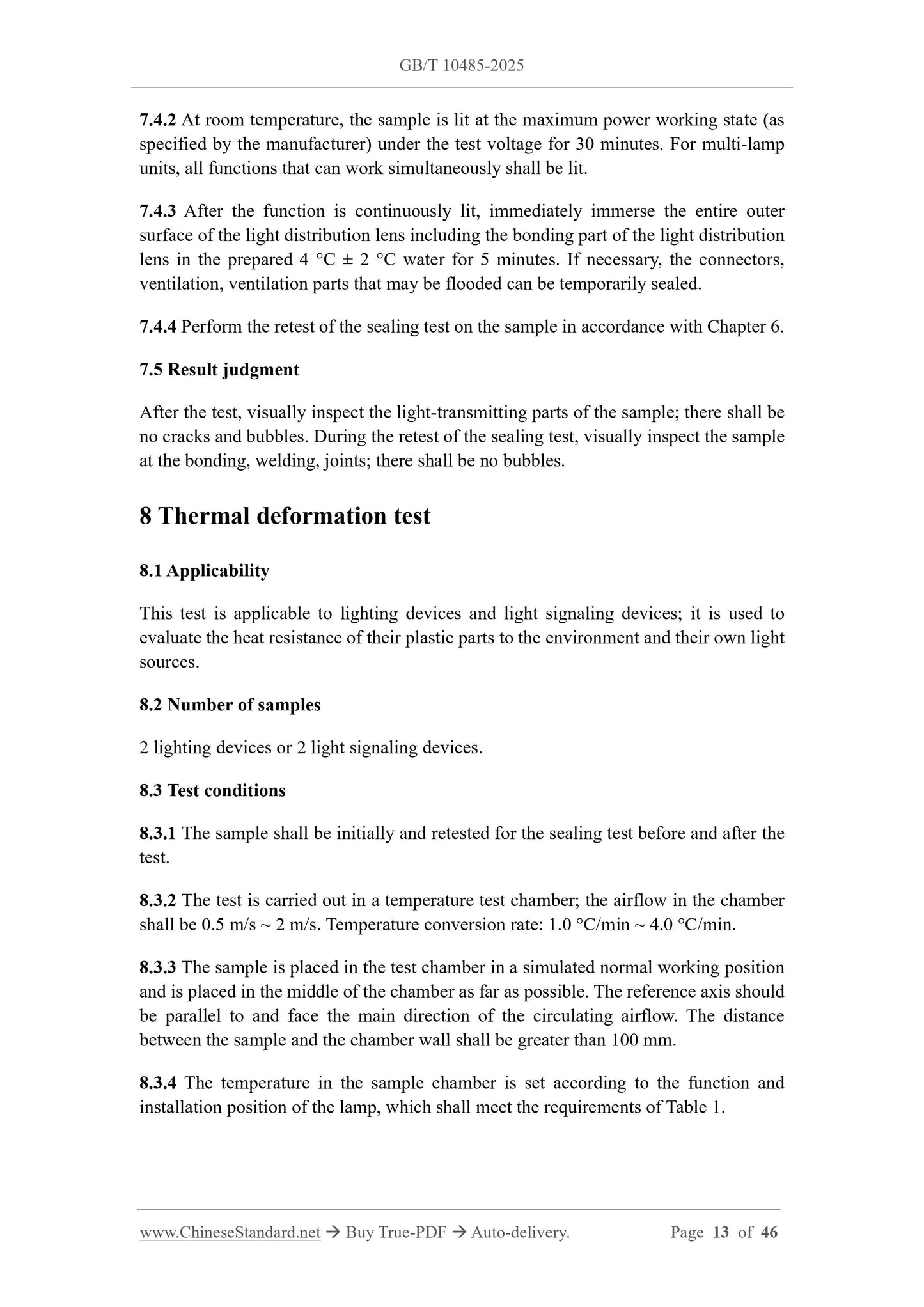
7.4.2 At room temperature, the sample is lit at the maximum power working state (as
specified by the manufacturer) under the test voltage for 30 minutes. For multi-lamp
units, all functions that can work simultaneously shall be lit.
7.4.3 After the function is continuously lit, immediately immerse the entire outer
surface of the light distribution lens including the bonding part of the light distribution
lens in the prepared 4 °C ± 2 °C water for 5 minutes. If necessary, the connectors,
ventilation, ventilation parts that may be flooded can be temporarily sealed.
7.4.4 Perform the retest of the sealing test on the sample in accordance with Chapter 6.
7.5 Result judgment
After the test, visually inspect the light-transmitting parts of the sample; there shall be
no cracks and bubbles. During the retest of the sealing test, visually inspect the sample
at the bonding, welding, joints; there shall be no bubbles.
8 Thermal deformation test
8.1 Applicability
This test is applicable to lighting devices and light signaling devices; it is used to
evaluate the heat resistance of their plastic parts to the environment and their own light
sources.
8.2 Number of samples
2 lighting devices or 2 light signaling devices.
8.3 Test conditions
8.3.1 The sample shall be initially and retested for the sealing test before and after the
test.
8.3.2 The test is carried out in a temperature test chamber; the airflow in the chamber
shall be 0.5 m/s ~ 2 m/s. Temperature conversion rate. 1.0 °C/min ~ 4.0 °C/min.
8.3.3 The sample is placed in the test chamber in a simulated normal working position
and is placed in the middle of the chamber as far as possible. The reference axis should
be parallel to and face the main direction of the circulating airflow. The distance
between the sample and the chamber wall shall be greater than 100 mm.
8.3.4 The temperature in the sample chamber is set according to the function and
installation position of the lamp, which shall meet the requirements of Table 1.
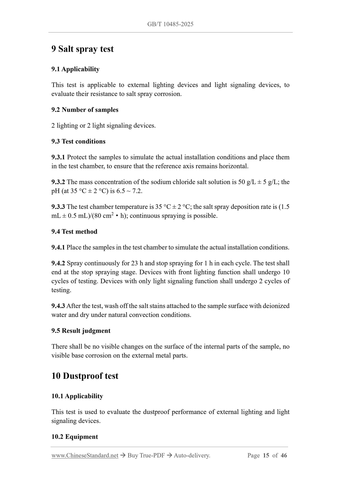
9 Salt spray test
9.1 Applicability
This test is applicable to external lighting devices and light signaling devices, to
evaluate their resistance to salt spray corrosion.
9.2 Number of samples
2 lighting or 2 light signaling devices.
9.3 Test conditions
9.3.1 Protect the samples to simulate the actual installation conditions and place them
in the test chamber, to ensure that the reference axis remains horizontal.
9.3.2 The mass concentration of the sodium chloride salt solution is 50 g/L ± 5 g/L; the
pH (at 35 °C ± 2 °C) is 6.5 ~ 7.2.
9.3.3 The test chamber temperature is 35 °C ± 2 °C; the salt spray deposition rate is (1.5
mL ± 0.5 mL)/(80 cm2·h); continuous spraying is possible.
9.4 Test method
9.4.1 Place the samples in the test chamber to simulate the actual installation conditions.
9.4.2 Spray continuously for 23 h and stop spraying for 1 h in each cycle. The test shall
end at the stop spraying stage. Devices with front lighting function shall undergo 10
cycles of testing. Devices with only light signaling function shall undergo 2 cycles of
testing.
9.4.3 After the test, wash off the salt stains attached to the sample surface with deionized
water and dry under natural convection conditions.
9.5 Result judgment
There shall be no visible changes on the surface of the internal parts of the sample, no
visible base corrosion on the external metal parts.
10 Dustproof test
10.1 Applicability
This test is used to evaluate the dustproof performance of external lighting and light
signaling devices.
10.2 Equipment
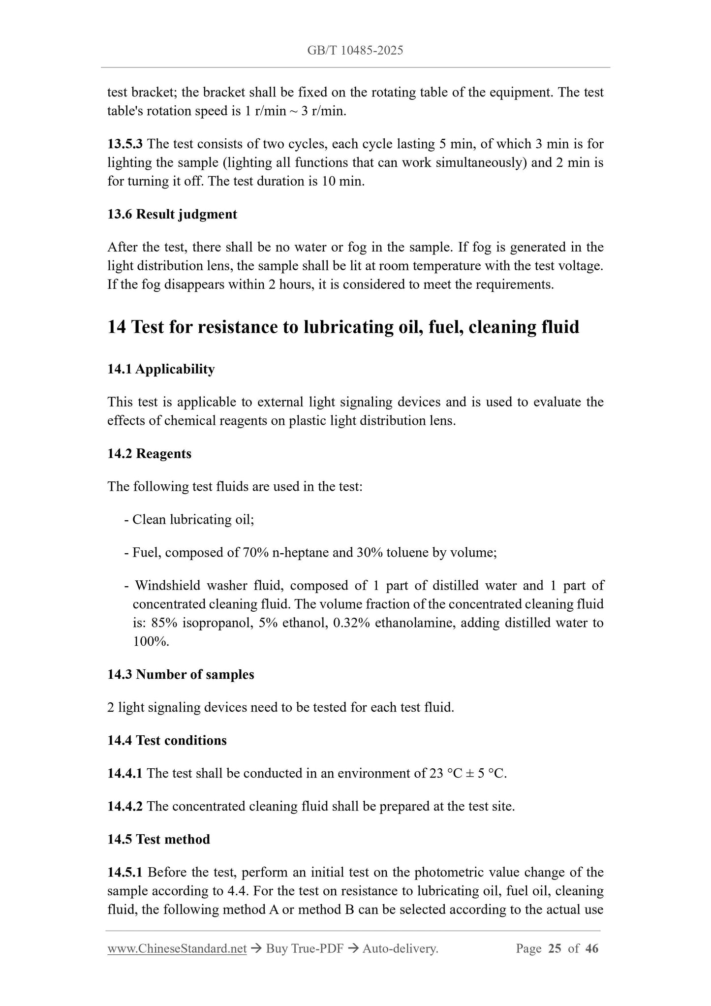
test bracket; the bracket shall be fixed on the rotating table of the equipment. The test
table's rotation speed is 1 r/min ~ 3 r/min.
13.5.3 The test consists of two cycles, each cycle lasting 5 min, of which 3 min is for
lighting the sample (lighting all functions that can work simultaneously) and 2 min is
for turning it off. The test duration is 10 min.
13.6 Result judgment
After the test, there shall be no water or fog in the sample. If fog is generated in the
light distribution lens, the sample shall be lit at room temperature with the test voltage.
If the fog disappears within 2 hours, it is considered to meet the requirements.
14 Test for resistance to lubricating oil, fuel, cleaning fluid
14.1 Applicability
This test is applicable to external light signaling devices and is used to evaluate the
effects of chemical reagents on plastic light distribution lens.
14.2 Reagents
The following test fluids are used in the test.
- Clean lubricating oil;
- Fuel, composed of 70% n-heptane and 30% toluene by volume;
- Windshield washer fluid, composed of 1 part of distilled water and 1 part of
concentrated cleaning fluid. The volume fraction of the concentrated cleaning fluid
is. 85% isopropanol, 5% ethanol, 0.32% ethanolamine, adding distilled water to
100%.
14.3 Number of samples
2 light signaling devices need to be tested for each test fluid.
14.4 Test conditions
14.4.1 The test shall be conducted in an environment of 23 °C ± 5 °C.
14.4.2 The concentrated cleaning fluid shall be prepared at the test site.
14.5 Test method
14.5.1 Before the test, perform an initial test on the photometric value change of the
sample according to 4.4.For the test on resistance to lubricating oil, fuel oil, cleaning
fluid, the following method A or method B can be selected according to the actual use
of the manufacturer's product.
- Method A. Contains two tests, 14.5.2 and 14.5.3.
- Method B. Contains three tests, 14.5.2, 14.5.3, 14.5.4.
14.5.2 Lubricating oil resistance test. Use a piece of cotton cloth soaked in clean
lubricating oil to wipe the outer surface of the sample's light distribution lens to make
it wet; wipe the surface clean after about 5 minutes; visually inspect the outer surface
of the light distribution lens. Perform the first retest on the photometric value change
of the sample according to 4.4.
14.5.3 Fuel resistance test. Use a cotton cloth soaked in fuel to wipe the outer surface
of the sample light distribution lens to make it wet; wipe the surface clean after about 5
minutes; visually inspect the outer surface of the lens. According to 4.4, retest the
photometric value change of the sample for the second time.
14.5.4 Cleaning fluid resistance test. Use a cotton cloth soaked in cleaning fluid to wipe
the outer surface of the sample light distribution lens to make it wet; inspect the outer
surface of the lens after 7 hours.
14.6 Result judgment
After the test, the outer surface of the light distribution lens shall be free of cracks,
discoloration, and deformation. After the lubricating oil resistance test, the photometric
value of the sample changes by no more than 20%. After the fuel resistance test, the
photometric value of the sample changes by no more than 20%.
15 Light source irradiation test
15.1 Applicability
This test is applicable to lighting devices (except headlights and front fog lights) and
light signaling devices installed on the outside of the vehicle; it is used to evaluate the
light source irradiation resistance of its plastic optical components.
15.2 Equipment
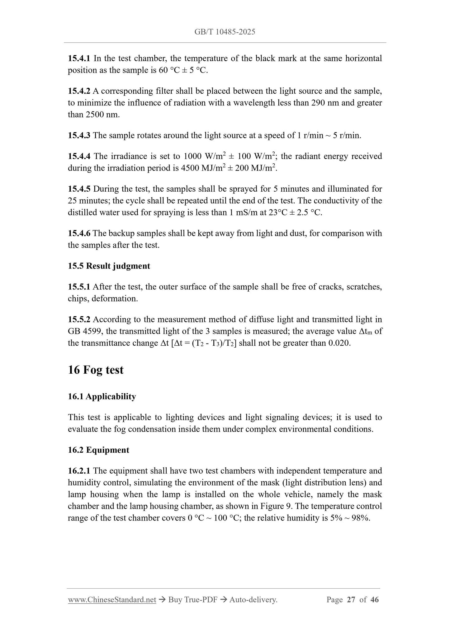
Weather agin...
Share