1
/
of
9
www.ChineseStandard.us -- Field Test Asia Pte. Ltd.
GB/T 10357.3-2013 English PDF (GB/T10357.3-2013)
Regular price
$125.00
Regular price
Sale price
$125.00
Unit price
/
per
Shipping calculated at checkout.
Couldn't load pickup availability
GB/T 10357.3-2013: Test of mechanical properties of furniture -- Part 3: Strength and durability of chairs and stools
Delivery: 9 seconds. Download (& Email) true-PDF + Invoice.
Get Quotation: Click GB/T 10357.3-2013 (Self-service in 1-minute)
Historical versions (Master-website): GB/T 10357.3-2013
Preview True-PDF (Reload/Scroll-down if blank)
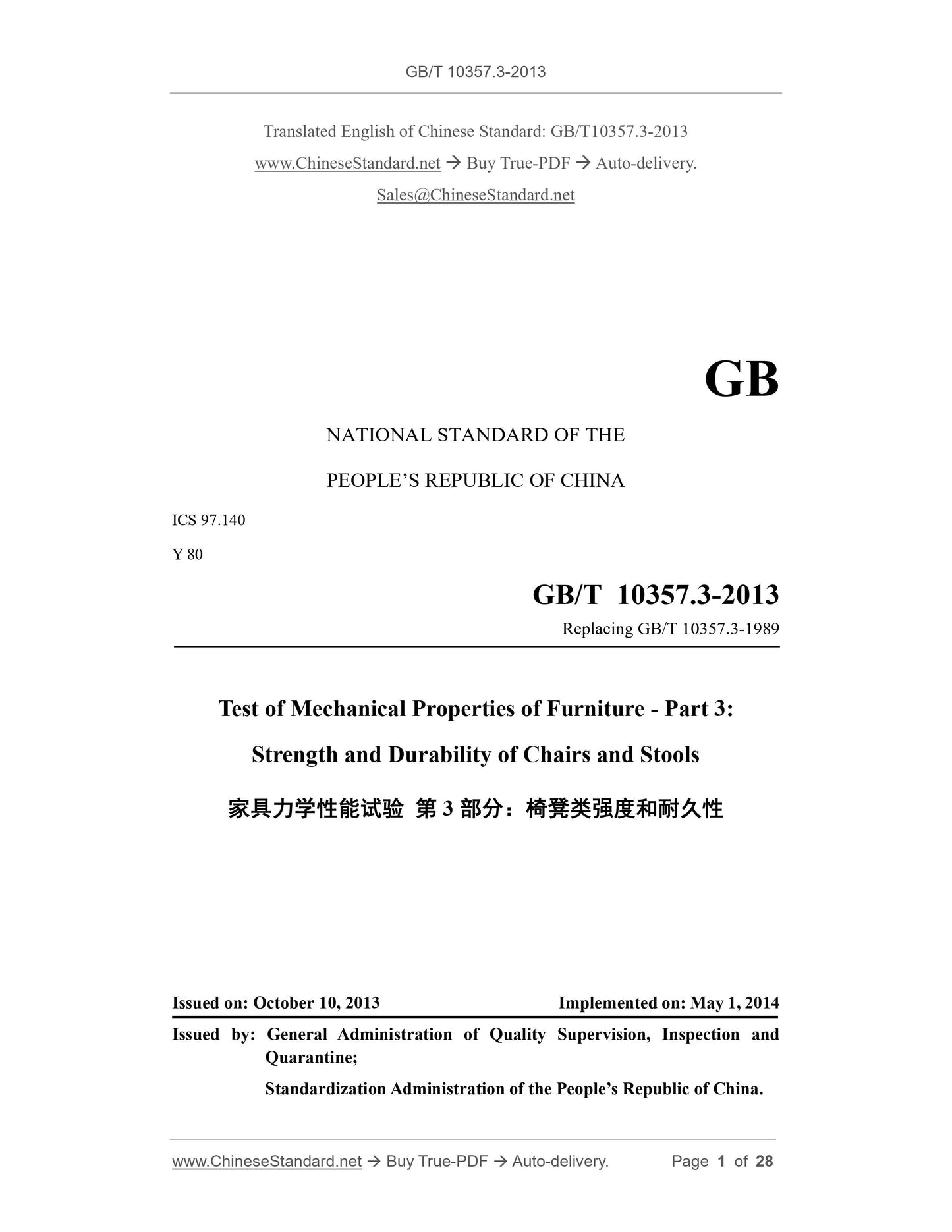
GB/T 10357.3-2013
GB
NATIONAL STANDARD OF THE
PEOPLE’S REPUBLIC OF CHINA
ICS 97.140
Y 80
Replacing GB/T 10357.3-1989
Test of Mechanical Properties of Furniture - Part 3:
Strength and Durability of Chairs and Stools
ISSUED ON: OCTOBER 10, 2013
IMPLEMENTED ON: MAY 1, 2014
Issued by: General Administration of Quality Supervision, Inspection and
Quarantine;
Standardization Administration of the People’s Republic of China.
Table of Contents
Foreword ... 3
1 Scope ... 5
2 General Test Conditions ... 5
3 Test Facilities ... 6
4 Test Items and Procedures ... 13
5 Assessment of Test Results ... 25
Appendix A (Informative) Test Level Selection Table ... 26
Appendix B (Normative) Summary Sheet of Test Items ... 27
Foreword
GB/T 10357 "Test of Mechanical Properties of Furniture" is divided into eight parts:
- Part 1: Strength and Durability of Tables;
- Part 2: Stability of Chairs and Stools;
- Part 3: Strength and Durability of Chairs and Stools;
- Part 4: Stability of Storage Units;
- Part 5: Strength and Durability of Storage Units;
- Part 6: Strength and Durability of Beds;
- Part 7: Stability of Tables;
- Part 8: Stability of Rocking Chairs and Chairs with Tilting or Reclining
Mechanisms When Fully Reclined.
This Part is Part 3 of GB/T 10357.
This Part is drafted according to the rules given in GB/T 1.1-2009.
This Part replaces GB/T 10357.3-1989 Test of Mechanical Properties of Furniture -
Strength and Durability of Chairs and Stools.
Compared with GB/T 10357.3-1989, the main technical changes in this Part are as
follows:
- The application scope of this Part is modified;
- Principle and test classification are deleted;
- The position of clause specifying the loading template is modified;
- Armrest durability test and its device are added;
- Precision requirement is modified and angle requirement is added;
- Methods of seat static load test and backrest static load test are modified and static
load test of front edge of seat is added;
- Static load tests of feet crosspiece/bracket and leg bracket are added;
- Armrest durability test is added;
Test of Mechanical Properties of Furniture - Part 3:
Strength and Durability of Chairs and Stools
1 Scope
This Part of GB/T 10357 specifies test methods for determining the strength and
durability of various chairs and stools.
This Part is applicable to various chairs and stools used in household, hotel and
restaurant.
This Part is not applicable to revolving chair, Children's chair as well as chairs and
stools made of ceramic, vine and osier.
2 General Test Conditions
2.1 Specimen
If the specimen is made by gluing timber or similar materials, after manufacture, it shall
be stored continuously in general indoor environment for at least 7d before the test.
Specimen shall be finished product. If the specimen is knock-down, the product shall
be assembled in accordance with assembly instruction; if the specimen may be
assembled or combined according to different modes, during the test, it shall be
assembled or combined according to the most adverse combination for the strength test
and durability test. Before the test, the connection piece of knock-down product shall
be fastened; the assembling components shall be firmly installed and cannot be
reinforced additionally without special requirements of manufacturer.
2.2 Loading requirements
The forces in strength tests shall be applied sufficiently slowly to ensure that negligible
dynamic load is applied. The forces in durability tests shall be applied sufficiently
slowly to ensure that kinetic heating does not occur. Unless otherwise specified, the
load shall be maintained for (10±2)s in strength test and shall be maintained for (2±1)s
in durability test.
2.3 Load
The test is divided into five levels according to the normal use frequency and potential
misusage degree of product under intended application conditions and based on the
magnitude and times of loading; the determination of test level is detailed in Appendix
A.
2.4 Test conditions
In addition to the specified test equipment, any suitable equipment is applicable to this
part. During running, the loading equipment for seat shall neither restrict the free
tipping of specimen, nor obstruct the horizontal movement of chair during backrest test.
All load pads shall rotate towards the direction of applied force and the rotation center
shall be close to the bearing surface as possible.
Each test shall be carried out on the same specimen according to the test procedures
specified in this part; in case that the specimen does not conform to the specified test
procedures due to its particular structures, the differences associated shall be recorded
in the test report.
Except for seat impact test, foam plastic pad may be positioned between the loading
pad and test equipment.
2.5 Precision requirements
Unless otherwise specified, the following measurement precision shall be adopted:
- Loading force: ±5% of the rated value;
- Mass: ±1% of the rated value;
- Dimension: ±1mm;
- Angle: ±2°;
- Positional accuracy of loading pad: ±5mm.
3 Test Facilities
3.1 Loading positioning template
Loading positioning template (see Figure 1 and Figure 2) is composed of two shaped
members fastened together by pivot at one end, and the loading point marks - A, B and
C are respectively marked on the template surface. The total load at the load point of
seat is 20kg.
Loading point A corresponds to the point 175mm forward from the seat and backrest
intersection point on the seat. Loading point B corresponds to the point 300mm upward
from the seat and backrest intersection point on the backrest. Loading point C
corresponds to the point on a stool as 175mm from one edge.
3.9.1 Cylinder
The cylinder, 200mm in diameter, connecting with the impact head through the spiral
compression spring assembly, moves relatively along the axis of the impact head
(central area). The mass of cylinder plus relevant accessories (excluding the springs) is
(17±0.1)kg; and the mass of the whole seat impactor (including the spiral compression
springs assembly and impact head) is (25±0.1)kg.
3.9.2 Spiral compression spring assembly
The rated elasticity coefficient of the spiral compression spring assembly shall be
(6.9±1)N/mm and the total friction resistance of the moving parts shall be 0.25~0.45N.
The pre-compression force of spiral compression spring assembly shall be (1040±5)N
and the amount of recompression shall not be less than 60mm.
3.9.3 Impact head
Rigid round object, 200mm in diameter, the loading surface of which is covered with
leather materials and filled with dry fine sand; the loading surface is spherical with
curvature radius of 300mm and with a peripheral rounding radius of 12mm.
3.10 Impact pendulum
Rigid cylindrical striker having a mass of 6.5kg, connected to the revolving shaft by a
steel tube, as the pendulum arm, of 38mm in external diameter and with a wall thickness
of 2mm. The distance between the rotation center of the pendulum and striker gravity
is 1m. The pendulum arm shall revolve through a low friction bearing (see Figure 7).
necessary, use the smaller seat loading pad. After the test, inspect the integral structure
of the specimen, then record and assess.
4.3.2 Backrest static load test
As shown in Figure 11, lean the stop against the foot side of chair or stool. Select the
corresponding test level of product and apply the load specified in Appendix B through
backrest loading pad in the direction vertical to the backrest for 10 times; for loading,
the balancing load on the seat shall be applied at the seat loading point determined by
the loading template; the balance force is generally 750N (75kg); if the chair tends to
overbalance, increase the balance force until this tendency ceases and record this
balance force. The loading position is in the lower one of the following two positions:
- Backrest loading point determined by the loading template;
- On the longitudinal backrest axis and with 100mm downward from the top of
backrest.
As for specimen with two or three backrests, as prescribed above, load as follows:
- As for specimen with two backrests, load on the two backrest loading points
simultaneously for 10 times;
- As for specimen with three backrests, load on the backrests on arbitrary one side
and middle simultaneously for 10 times.
The loading force each time shall be maintained for at least 10s.
Backrest static load shall not be less than 410N.
When this test is applied to a stool with rectangular underframes, regardless of the shape
of the seat, apply the force successively to the front edge of seat corresponding to each
midpoint of the two sides adjacent to the rectangular underframes for 5 times,
respectively. For stools with triangular underframes, apply the force successively along
arbitrary two center lines for 5 times respectively.
After the test, remove the force applied on the backrest firstly and then remove the force
applied on the seat. Inspect the integral structure of specimen, then record and assess.
Combined or separate static load test may be carried out for backrest and seat.
4.3.3 Static load test of front edge of seat
Where only seat static load is applied, apply vertical downward load of appropriate test
level specified in the table of Appendix A for 10 times at the point 80mm backward
from the center line of this front edge of seat or at the most unfavorable position not
more than 80mm from the seat’s edge. The loading force each time shall be maintained
for at least 10s.
After the test, inspect the integral structure of the specimen, then record and assess.
Note: Separate or combined static load test may be carried out for backrest and seat.
4.4 Static load tests of feet crosspiece/bracket and leg bracket
Apply specific loading force at the most vulnerable position on the periphery 80mm
upward from the center line of feet bracket, leg bracket or feet crosspiece by using
smaller seat loading pad. Apply force for 10 times in total.
If the specimen tends to overbalance, decrease the loading force until this tendency
ceases and record the actual applied force.
After the test, inspect the integral structure of the specimen, then record and assess.
4.5 Armrest and headrest sideways static load test
Apply a pair of outward forces specified in the Table B.1 for 10 times at the point along
the armrests most likely to cause failure through the smaller loading pad (see Figure
12). During each application, maintain the load for at least 10s. If the chair has headrests
(i.e. two side pieces at the top of an armchair against which the head may be rested),
apply the force specified in Table B.1 on both headrests.
Note: Since the loading position for seat load and the loading cycle in the seat durability test is the same
as that in the backrest durability test, these two tests may be performed together as a combined test. In
this case, in each loading/unloading cycle, the seat load shall be applied first and then the backrest load;
and for the unloading, the backrest shall be the first and then the seat.
When this test is applied to a chair fitted with a spring rocking action base that has a
tension adjustment, set the spring tension to the midpoint of the adjustable range during
the test.
When this test is applied to a stool or a chair with a very low backrest, apply the
backward force horizontally to the midpoint of front edge of seat. As for stools with
four legs on which the seat surface is not symmetrical both longitudinally and
transversally, apply the force for half of the loading times respectively in the directions
of the two longitudinal and transversal axis of symmetry along the seat. As for stools
with three legs, apply forces along two of the principle axis of symmetry.
After the test, inspect the integral structure of specimen, then record and assess.
4.9 Armrest durability test
Place the chair on the test floor and place stops at outside of its leg, trundle or sliding
rail. The stop cannot prevent inward displacement of chair leg during armrest loading.
Take two points at 100mm backward from the front edge of armrest and apply force
simultaneously. Apply load of 10N with devices in Section 3.11. Angle of 10°±1° is
formed by the load and vertical surface, the horizontal distance between the friction
revolving shaft and armrest loading device is (600±10)mm (see Figure 16).
GB/T 10357.3-2013
GB
NATIONAL STANDARD OF THE
PEOPLE’S REPUBLIC OF CHINA
ICS 97.140
Y 80
Replacing GB/T 10357.3-1989
Test of Mechanical Properties of Furniture - Part 3:
Strength and Durability of Chairs and Stools
ISSUED ON: OCTOBER 10, 2013
IMPLEMENTED ON: MAY 1, 2014
Issued by: General Administration of Quality Supervision, Inspection and
Quarantine;
Standardization Administration of the People’s Republic of China.
Table of Contents
Foreword ... 3
1 Scope ... 5
2 General Test Conditions ... 5
3 Test Facilities ... 6
4 Test Items and Procedures ... 13
5 Assessment of Test Results ... 25
Appendix A (Informative) Test Level Selection Table ... 26
Appendix B (Normative) Summary Sheet of Test Items ... 27
Foreword
GB/T 10357 "Test of Mechanical Properties of Furniture" is divided into eight parts:
- Part 1: Strength and Durability of Tables;
- Part 2: Stability of Chairs and Stools;
- Part 3: Strength and Durability of Chairs and Stools;
- Part 4: Stability of Storage Units;
- Part 5: Strength and Durability of Storage Units;
- Part 6: Strength and Durability of Beds;
- Part 7: Stability of Tables;
- Part 8: Stability of Rocking Chairs and Chairs with Tilting or Reclining
Mechanisms When Fully Reclined.
This Part is Part 3 of GB/T 10357.
This Part is drafted according to the rules given in GB/T 1.1-2009.
This Part replaces GB/T 10357.3-1989 Test of Mechanical Properties of Furniture -
Strength and Durability of Chairs and Stools.
Compared with GB/T 10...
Share