1
/
of
12
www.ChineseStandard.us -- Field Test Asia Pte. Ltd.
GB/T 1029-2021 English PDF (GB/T1029-2021)
Regular price
$1,305.00
Regular price
Sale price
$1,305.00
Unit price
/
per
Shipping calculated at checkout.
Couldn't load pickup availability
GB/T 1029-2021: Test procedures for three-phase synchronous machines
Delivery: 9 seconds. Download (& Email) true-PDF + Invoice.
Get Quotation: Click GB/T 1029-2021 (Self-service in 1-minute)
Historical versions (Master-website): GB/T 1029-2021
Preview True-PDF (Reload/Scroll-down if blank)
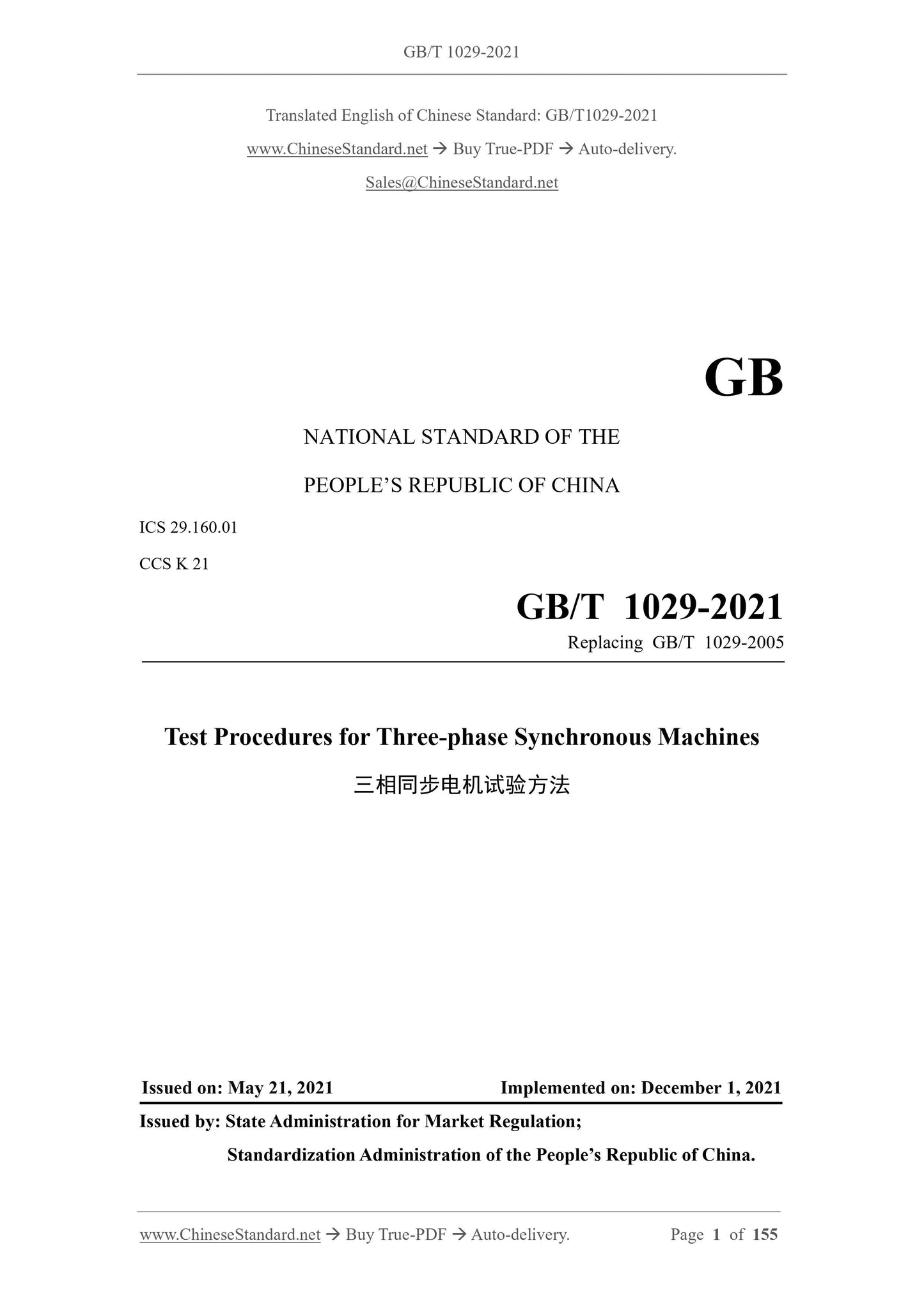
GB/T 1029-2021
GB
NATIONAL STANDARD OF THE
PEOPLE’S REPUBLIC OF CHINA
ICS 29.160.01
CCS K 21
Replacing GB/T 1029-2005
Test Procedures for Three-phase Synchronous Machines
ISSUED ON: MAY 21, 2021
IMPLEMENTED ON: DECEMBER 1, 2021
Issued by: State Administration for Market Regulation;
Standardization Administration of the People’s Republic of China.
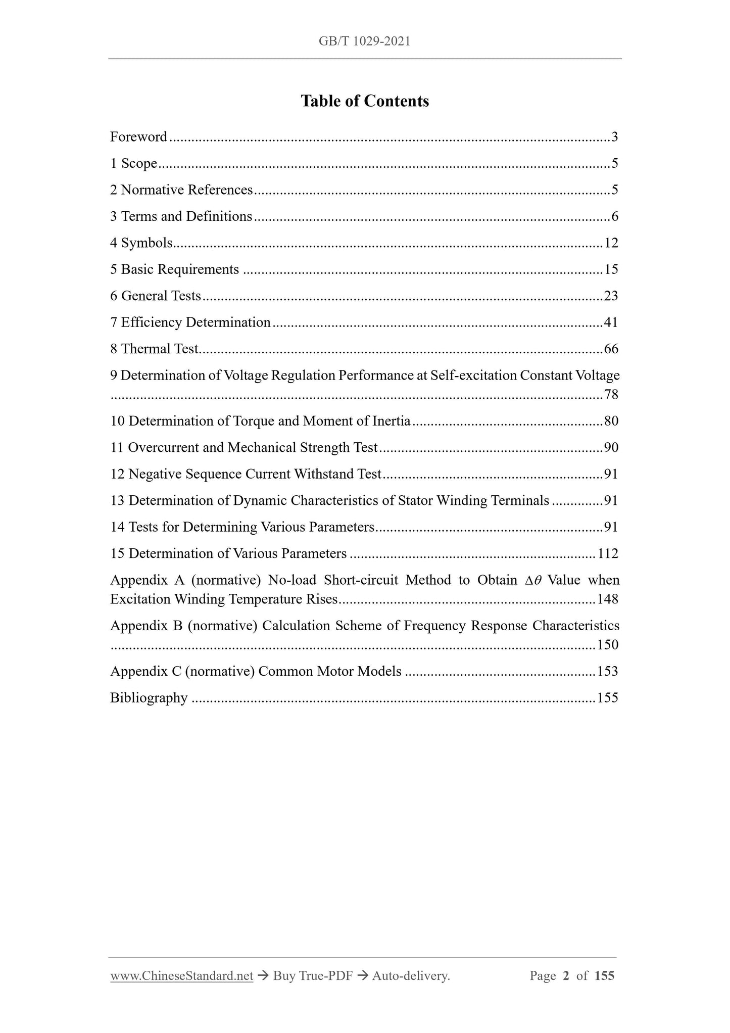
Table of Contents
Foreword ... 3
1 Scope ... 5
2 Normative References ... 5
3 Terms and Definitions ... 6
4 Symbols ... 12
5 Basic Requirements ... 15
6 General Tests ... 23
7 Efficiency Determination ... 41
8 Thermal Test ... 66
9 Determination of Voltage Regulation Performance at Self-excitation Constant Voltage
... 78
10 Determination of Torque and Moment of Inertia ... 80
11 Overcurrent and Mechanical Strength Test ... 90
12 Negative Sequence Current Withstand Test ... 91
13 Determination of Dynamic Characteristics of Stator Winding Terminals ... 91
14 Tests for Determining Various Parameters ... 91
15 Determination of Various Parameters ... 112
Appendix A (normative) No-load Short-circuit Method to Obtain Value when
Excitation Winding Temperature Rises ... 148
Appendix B (normative) Calculation Scheme of Frequency Response Characteristics
... 150
Appendix C (normative) Common Motor Models ... 153
Bibliography ... 155
Test Procedures for Three-phase Synchronous Machines
1 Scope
This document describes the test methods for three-phase synchronous motors, including
general test, efficiency determination, thermal test, voltage regulation performance
determination during self-excitation constant voltage, determination of rotation and torque
inertia, overcurrent and mechanical strength tests, negative sequence current bearing capacity
test, determination of dynamic characteristics of stator winding terminals, and tests for
determining various parameters, etc.
This document is applicable to three-phase synchronous motors with a rated power of 1 kW
(kVA).
2 Normative References
The contents of the following documents constitute indispensable clauses of this document
through the normative references in the text. In terms of references with a specified date, only
versions with a specified date are applicable to this document. In terms of references without a
specified date, the latest version (including all the modifications) is applicable to this document.
GB/T 755-2019 Rotating Electrical Machines - Rating and Performance
GB/T 7409.3 Excitation System for Synchronous Electrical Machines - Technical
Requirements of Excitation System for Large and Medium Synchronous Generators
GB/T 10068 Mechanical Vibration of Certain Machines with Shaft Heights 56 mm and Higher
- Measurement, Evaluation and Limits of Vibration Severity
GB/T 10069.1 Measurement of the Airborne Noise Emitted by Rotating Electrical Machines
and the Noise Limits - Part 1: Method for the Measurement of Airborne Noise Emitted by
Rotating Electrical Machines
GB/T 10585 Fundamental Requirements of Excitation Systems for Medium and Small
Synchronous Machines
GB/T 15548 General Specification for Three-phase Synchronous Generators Driven by
Reciprocating Internal Combustion Engine
GB/T 21211 Equivalent Loading and Superposition Techniques - Indirect Testing to Determine
Temperature Rise of Rotating Electrical Machines
GB/T 22715 Impulse Voltage Withstand Levels of Form-wound Stator Coils for Rotating a.c.
Machines
[source: GB/T 2900.25-2008, 411-48-27]
3.23 direct-axis transient short-circuit time constant
When the motor operates at a rated speed, and the operating conditions suddenly change, the
time required for the gradual component of the direct-axis short-circuit armature winding
current to attenuate to 1/e, i.e., 0.368 times, of its initial value.
[source: GB/T 2900.25-2008, 411-48-28]
3.24 direct-axis sub-transient open-circuit time constant
When the motor operates at a rated speed, and the operating conditions suddenly change, the
time required for the rapidly changing component of the armature winding open-circuit voltage
generated by the direct-axis magnetic flux that emerges in the first few weeks to attenuate to
1/e, i.e., 0.368 times, of its initial value.
[source: GB/T 2900.25-2008, 411-48-29]
3.25 direct-axis sub-transient short-circuit time constant
When the motor operates at a rated speed, and the operating conditions suddenly change, the
time required for the rapidly changing component of the direct-axis short-circuit armature
current that emerges in the first few weeks to attenuate to 1/e, i.e., 0.368 times, of its initial
value.
[source: GB/T 2900.25-2008, 411-48-30]
3.26 quadrature-axis transient open-circuit time constant
When the motor operates at a rated speed, and the operating conditions suddenly change, the
time required for the gradual component of the armature winding open-circuit voltage generated
by the quadrature-axis magnetic flux to attenuate to 1/e, i.e., 0.368 times, of its initial value.
[source: GB/T 2900.25-2008, 411-48-32]
3.27 quadrature-axis transient short-circuit time constant
When the motor operates at a rated speed, and the operating conditions suddenly change, the
time required for the gradual component of the quadrature-axis short-circuit armature winding
current to attenuate to 1/e, i.e., 0.368 times, of its initial value.
[source: GB/T 2900.25-2008, 411-48-33]
3.28 quadrature-axis sub-transient open-circuit time constant
When the motor operates at a rated speed, and the operating conditions suddenly change, the
time required for the rapidly changing component of the armature winding open-circuit voltage
generated by the quadrature-axis magnetic flux to attenuate to 1/e, i.e., 0.368 times, of its initial
value.
[source: GB/T 2900.25-2008, 411-48-34]
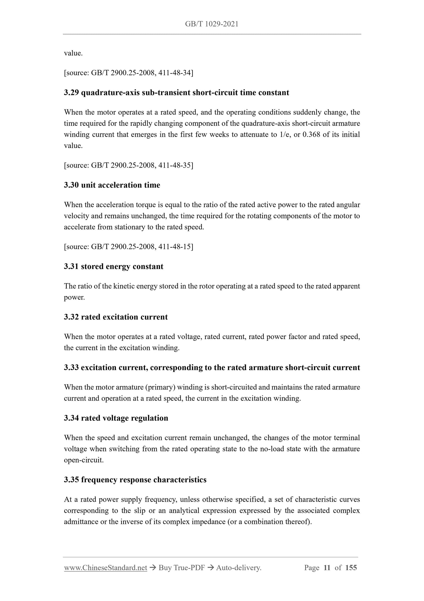
3.29 quadrature-axis sub-transient short-circuit time constant
When the motor operates at a rated speed, and the operating conditions suddenly change, the
time required for the rapidly changing component of the quadrature-axis short-circuit armature
winding current that emerges in the first few weeks to attenuate to 1/e, or 0.368 of its initial
value.
[source: GB/T 2900.25-2008, 411-48-35]
3.30 unit acceleration time
When the acceleration torque is equal to the ratio of the rated active power to the rated angular
velocity and remains unchanged, the time required for the rotating components of the motor to
accelerate from stationary to the rated speed.
[source: GB/T 2900.25-2008, 411-48-15]
3.31 stored energy constant
The ratio of the kinetic energy stored in the rotor operating at a rated speed to the rated apparent
power.
3.32 rated excitation current
When the motor operates at a rated voltage, rated current, rated power factor and rated speed,
the current in the excitation winding.
3.33 excitation current, corresponding to the rated armature short-circuit current
When the motor armature (primary) winding is short-circuited and maintains the rated armature
current and operation at a rated speed, the current in the excitation winding.
3.34 rated voltage regulation
When the speed and excitation current remain unchanged, the changes of the motor terminal
voltage when switching from the rated operating state to the no-load state with the armature
open-circuit.
3.35 frequency response characteristics
At a rated power supply frequency, unless otherwise specified, a set of characteristic curves
corresponding to the slip or an analytical expression expressed by the associated complex
admittance or the inverse of its complex impedance (or a combination thereof).
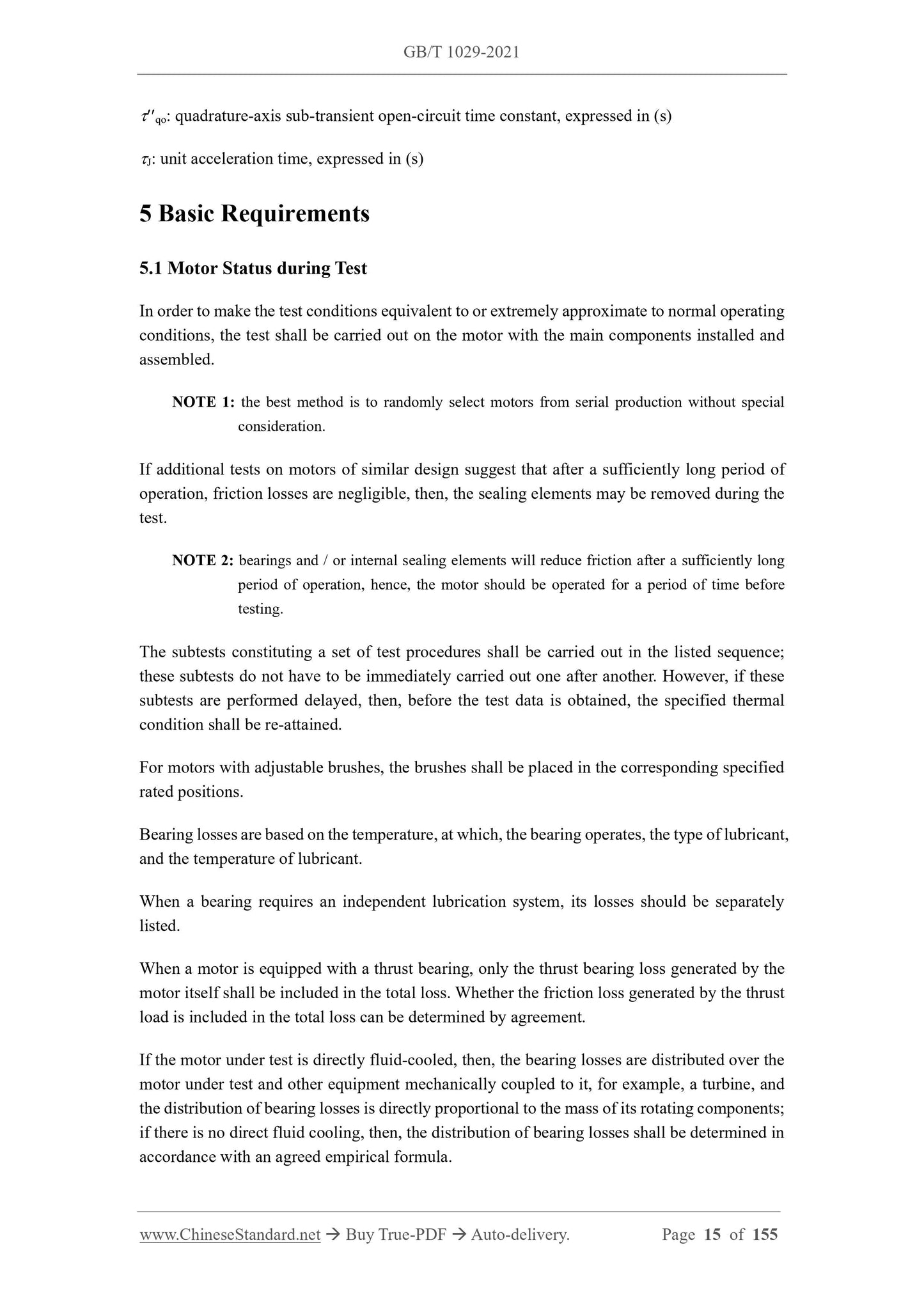
qo: quadrature-axis sub-transient open-circuit time constant, expressed in (s)
J: unit acceleration time, expressed in (s)
5 Basic Requirements
5.1 Motor Status during Test
In order to make the test conditions equivalent to or extremely approximate to normal operating
conditions, the test shall be carried out on the motor with the main components installed and
assembled.
NOTE 1: the best method is to randomly select motors from serial production without special
consideration.
If additional tests on motors of similar design suggest that after a sufficiently long period of
operation, friction losses are negligible, then, the sealing elements may be removed during the
test.
NOTE 2: bearings and / or internal sealing elements will reduce friction after a sufficiently long
period of operation, hence, the motor should be operated for a period of time before
testing.
The subtests constituting a set of test procedures shall be carried out in the listed sequence;
these subtests do not have to be immediately carried out one after another. However, if these
subtests are performed delayed, then, before the test data is obtained, the specified thermal
condition shall be re-attained.
For motors with adjustable brushes, the brushes shall be placed in the corresponding specified
rated positions.
Bearing losses are based on the temperature, at which, the bearing operates, the type of lubricant,
and the temperature of lubricant.
When a bearing requires an independent lubrication system, its losses should be separately
listed.
When a motor is equipped with a thrust bearing, only the thrust bearing loss generated by the
motor itself shall be included in the total loss. Whether the friction loss generated by the thrust
load is included in the total loss can be determined by agreement.
If the motor under test is directly fluid-cooled, then, the bearing losses are distributed over the
motor under test and other equipment mechanically coupled to it, for example, a turbine, and
the distribution of bearing losses is directly proportional to the mass of its rotating components;
if there is no direct fluid cooling, then, the distribution of bearing losses shall be determined in
accordance with an agreed empirical formula.
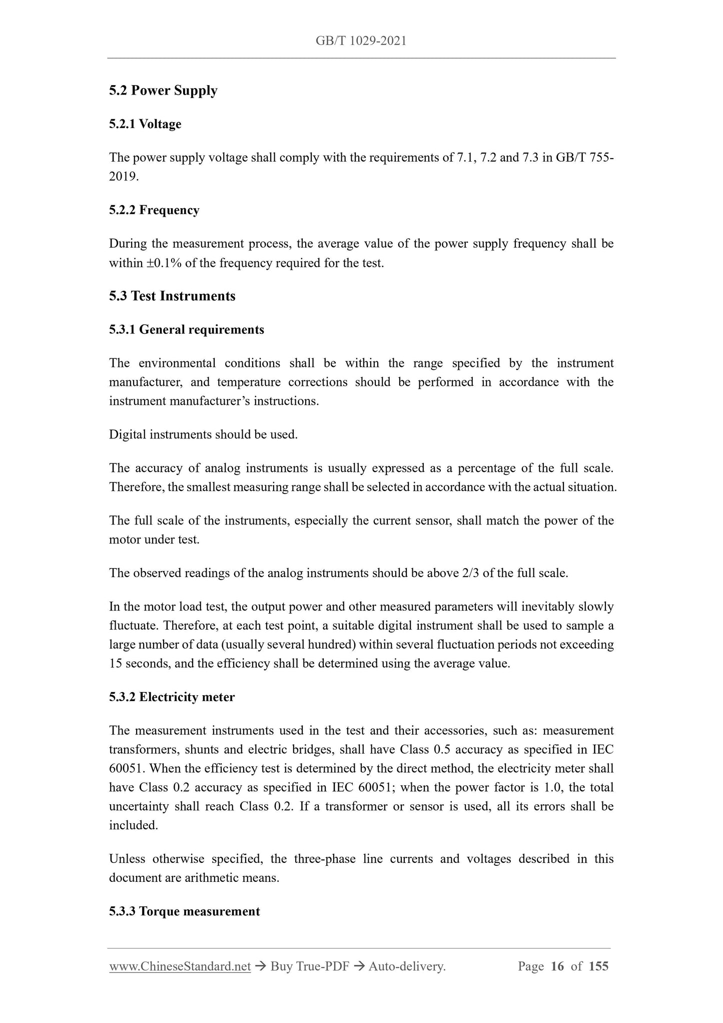
5.2 Power Supply
5.2.1 Voltage
The power supply voltage shall comply with the requirements of 7.1, 7.2 and 7.3 in GB/T 755-
2019.
5.2.2 Frequency
During the measurement process, the average value of the power supply frequency shall be
within 0.1% of the frequency required for the test.
5.3 Test Instruments
5.3.1 General requirements
The environmental conditions shall be within the range specified by the instrument
manufacturer, and temperature corrections should be performed in accordance with the
instrument manufacturer’s instructions.
Digital instruments should be used.
The accuracy of analog instruments is usually expressed as a percentage of the full scale.
Therefore, the smallest measuring range shall be selected in accordance with the actual situation.
The full scale of the instruments, especially the current sensor, shall match the power of the
motor under test.
The observed readings of the analog instruments should be above 2/3 of the full scale.
In the motor load test, the output power and other measured parameters will inevitably slowly
fluctuate. Therefore, at each test point, a suitable digital instrument shall be used to sample a
large number of data (usually several hundred) within several fluctuation periods not exceeding
15 seconds, and the efficiency shall be determined using the average value.
5.3.2 Electricity meter
The measurement instruments used in the test and their accessories, such as: measurement
transformers, shunts and electric bridges, shall have Class 0.5 accuracy as specified in IEC
60051. When the efficiency test is determined by the direct method, the electricity meter shall
have Class 0.2 accuracy as specified in IEC 60051; when the power factor is 1.0, the total
uncertainty shall reach Class 0.2. If a transformer or sensor is used, all its errors shall be
included.
Unless otherwise specified, the three-phase line currents and voltages described in this
document are arithmetic means.
5.3.3 Torque measurement
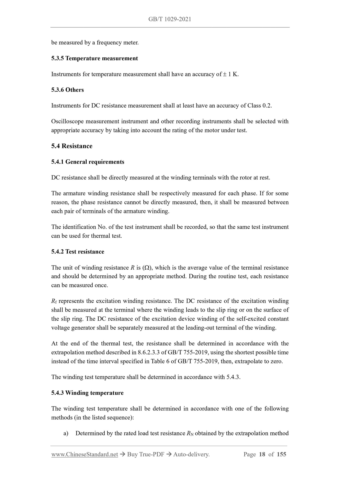
be measured by a frequency meter.
5.3.5 Temperature measurement
Instruments for temperature measurement shall have an accuracy of 1 K.
5.3.6 Others
Instruments for DC resistance measurement shall at least have an accuracy of Class 0.2.
Oscilloscope measurement instrument and other recording instruments shall be selected with
appropriate accuracy by taking into account the rating of the motor under test.
5.4 Resistance
5.4.1 General requirements
DC resistance shall be directly measured at the winding terminals with the rotor at rest.
The armature winding resistance shall be respectively measured for each phase. If for some
reason, the phase resistance cannot be directly measured, then, it shall be measured between
each pair of terminals of the armature winding.
The identification No. of the test instrument shall be recorded, so that the same test instrument
can be used for thermal test.
5.4.2 Test resistance
The unit of winding resistance R is (), which is the average value of the terminal resistance
and should be determined by an appropriate method. During the routine test, each resistance
can be measured once.
Rf represents the excitation winding resistance. The DC resistance of the excitation winding
shall be measured at the terminal where the winding leads to the slip ring or on the surface of
the slip ring. The DC resistance of the excitation device winding of the self-excited constant
voltage generator shall be separately measured at the leading-out terminal of the winding.
At the end of the thermal test, the resistance shall be determined in accordance with the
extrapolation method described in 8.6.2.3.3 of GB/T 755-2019, using the shortest possible time
instead of the time interval specified in Table 6 of GB/T 755-2019, then, extrapolate to zero.
The winding test temperature shall be determined in accordance with 5.4.3.
5.4.3 Winding temperature
The winding test temperature shall be determined in accordance with one of the following
methods (in the listed sequence):
a) Determined by the rated load test resistance RN obtained by the extrapolation method
For copper windings, the temperature constant is 235. For aluminum windin...
Share