1
/
of
6
www.ChineseStandard.us -- Field Test Asia Pte. Ltd.
GB 7251.6-2015 English PDF
GB 7251.6-2015 English PDF
Regular price
$145.00
Regular price
Sale price
$145.00
Unit price
/
per
Shipping calculated at checkout.
Couldn't load pickup availability
GB 7251.6-2015: [GB/T 7251.6-2015] Low-voltage switchgear and controlgear assemblies -- Part 6: Busbar trunking systems (busways)
Delivery: 9 seconds. Download (& Email) true-PDF + Invoice.
Get Quotation: Click GB 7251.6-2015 (Self-service in 1-minute)
Historical versions (Master-website): GB 7251.6-2015
Preview True-PDF (Reload/Scroll-down if blank)
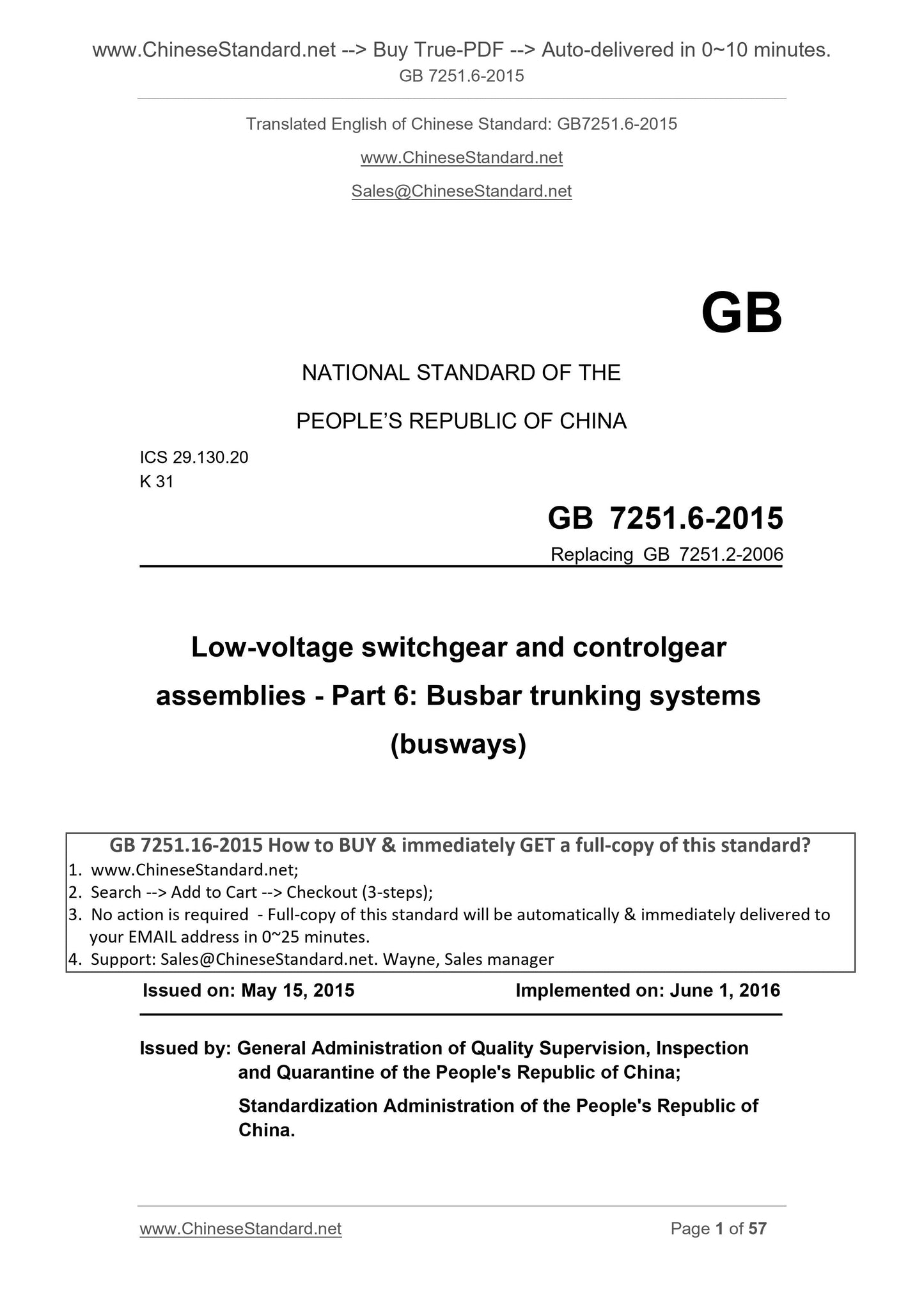
GB 7251.6-2015
Low-voltage switchgear and controlgear assemblies - Part 6. Busbar trunking systems (busways)
ICS 29.130.20
K31
National Standards of People's Republic of China
Replacing GB 7251.2-2006
Low-voltage switchgear and control equipment
Part 6. busbar trunking systems (busways)
Part 6. Busbartrunkingsystems (busways)
Issued on. 2015-05-15
2016-06-01 implementation
Administration of Quality Supervision, Inspection and Quarantine of People's Republic of China
Standardization Administration of China released
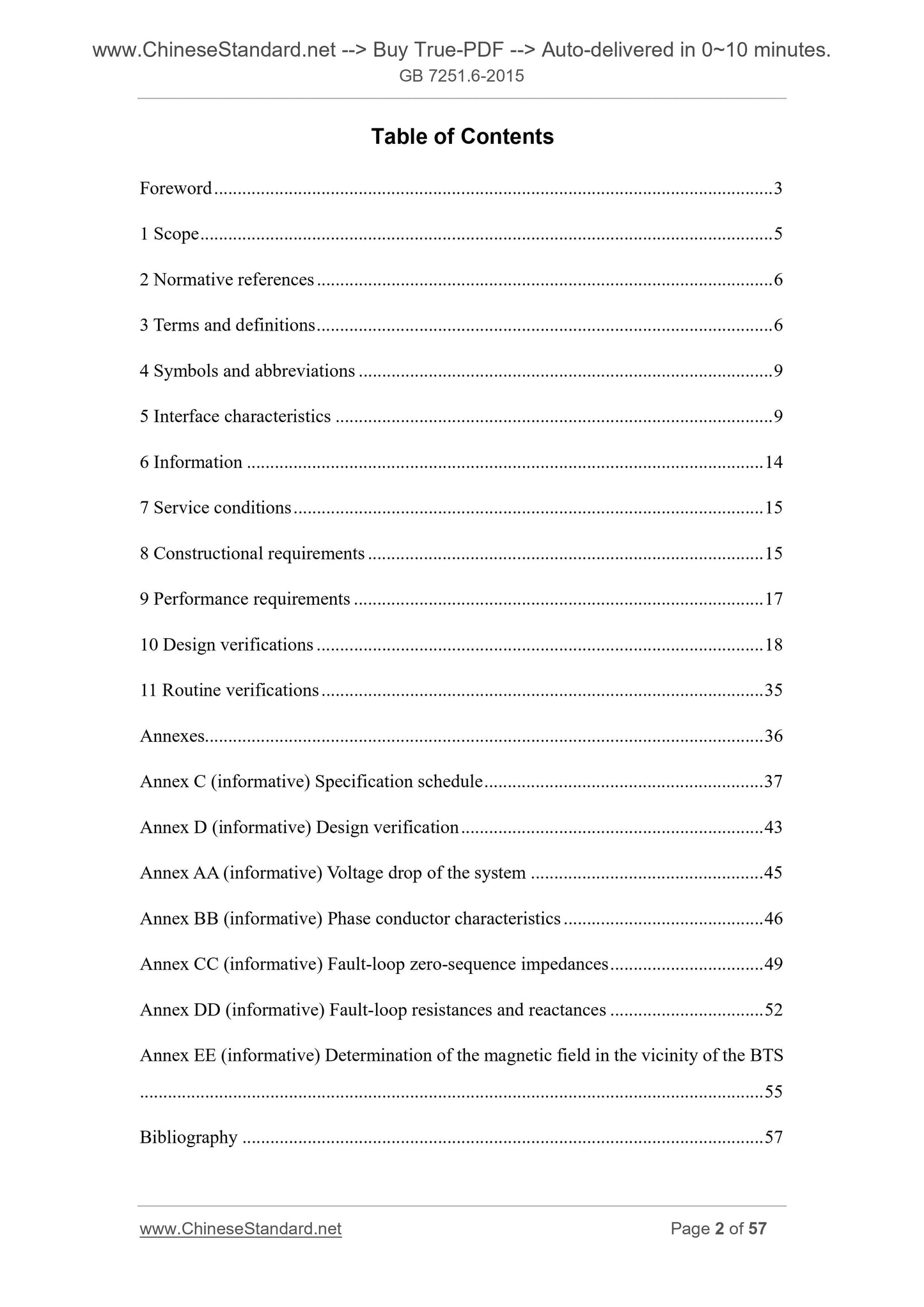
Table of Contents
Introduction Ⅲ
1 Scope 1
2 Normative references 1
3 Terms and definitions 2
4 Symbols and abbreviations 3
5 3 interface characteristics
7 7 conditions of use
8 structural requirements
9 Performance requirements
10 9 Design Verification
11 19 Routine Tests
Appendix 20
Annex C (informative) Specification Table 21
Annex D (informative) design verification 25
Voltage Annex AA (informative) drop across the system 26
Appendix BB (informative) phase conductor properties 27
Annex CC (informative) fault zero sequence impedance 29
Appendix DD (informative) fault loop resistance and reactance 31
The magnetic field near the appendix EE (informative) busbar trunking system determines 33
References 34
101 straight section 10 of the mechanical load test
102 mechanical load test connection points 10
103 flame test verification arrangements baffle busbar trunking unit 19
Figure BB.1 phase conductor characteristic determination 27
Figure CC.1 fault zero sequence impedance is determined 29
Figure DD.1 fault loop resistance and reactance determined 31
Figure EE.1 magnetic field measurement arrangement 33
Table 101 tap unit nominal dispersion coefficient 5
Table 5 Characteristics of phase conductor 102
Table 103 Fault loop characteristics 6
104 Characteristics Table 6 for fault current calculations
Thermal cycle test conditions 105 Table 12
Table C.1 user specifications Table 21
Table D.1 Design Verification 25
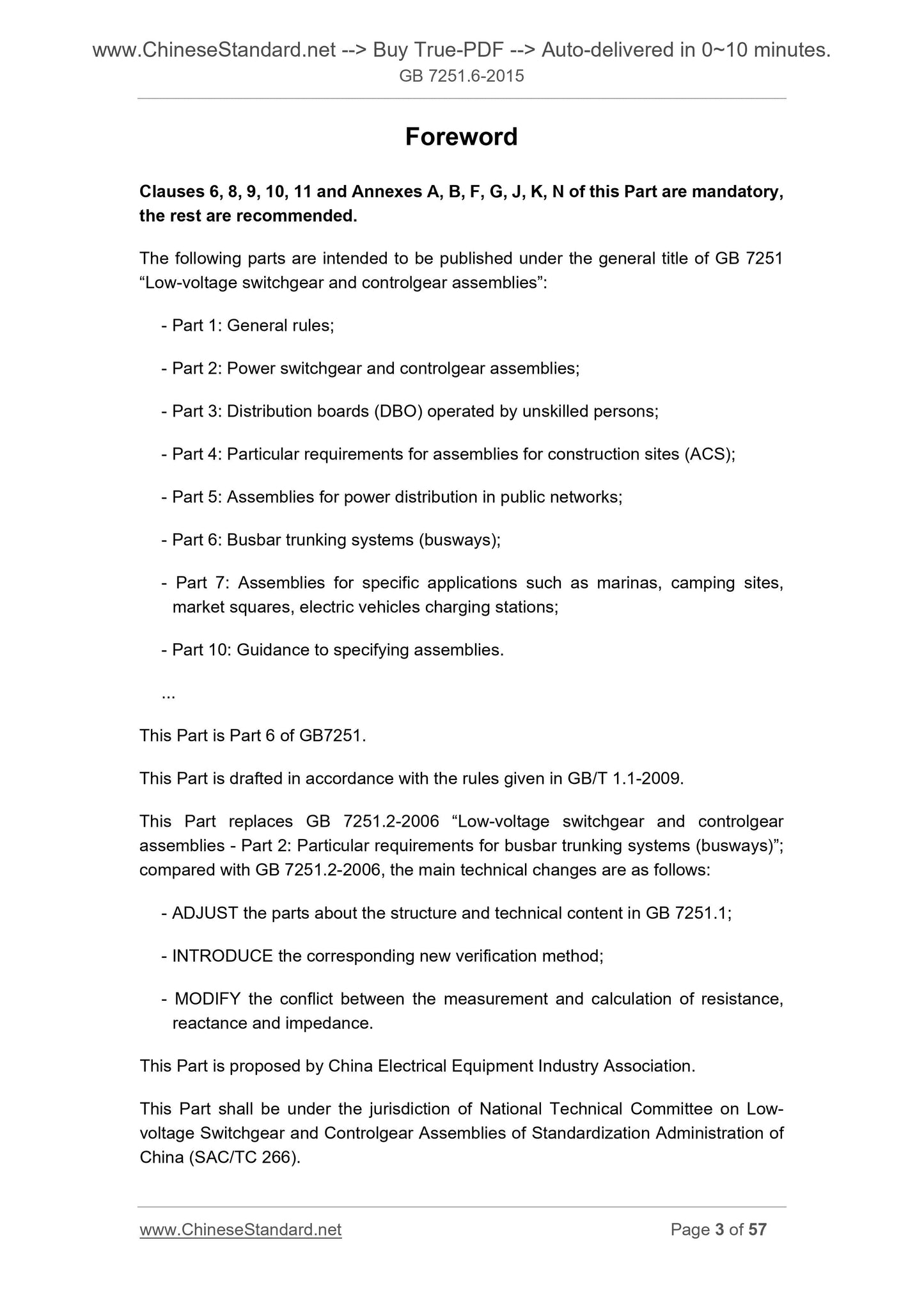
Foreword
Section 6 of this chapter, Chapter 8, Chapter 9, Chapter 10, Chapter 11, Appendix A, Appendix B, Appendix F, Appendix G, Appendix J, Appendix K,
Appendix N mandatory, the rest are recommended.
GB 7251 "Low-voltage switchgear and control equipment" series of standard plans to release the following components.
--- Part 1. General;
--- Part 2. Complete power switching and control equipment;
--- Part 3. by the general staff of the switchboard operator (DBO);
--- Part 4. Particular requirements for construction sites with equipment (ACS); and
--- Part 5. utility grid power distribution equipment;
--- Part 6. busbar trunking systems (busways);
--- Part 7. equipment for specific applications --- such as docks, campgrounds, Market Square, electric vehicle charging stations;
--- Part 10. Guide to the provisions of complete sets of equipment.
This is Part 6 GB 7251's.
This section drafted in accordance with GB/T 1.1-2009 given rules.
This Part replaces GB 7251.2-2006 "Low-voltage switchgear and control equipment Part 2. busbar trunking systems (bus
Groove) special requirements ", compared with GB 7251.2-2006, the main technical changes are as follows.
--- Adjustment GB 7251.1 in part on the structure and technical content;
--- Introduce appropriate new verification methods;
--- Modify resistance, reactance and impedance measurement and calculation of contradictions.
This part is proposed by the China Electrical Equipment Industrial Association.
This part of the National Low-voltage switchgear and control equipment Standardization Technical Committee (SAC/TC266) centralized.
This section is drafted. Tianjin Electric Drive Design Institute Co., Ltd., Tianjin-day electric power distribution Ltd, state-controlled electricity distribution
Equipment Quality Supervision and Inspection Center, Daquan Group Co., Ltd., Yuyao electrical equipment built factory, China Quality Certification Center, Guangzhou radius electricity
Power Copper Co., Ltd., Jiangsu Huapeng Zhi can Electric Co., Ltd., Gansu Electric Apparatus Research Institute, Chengdu Branch Star Electric Power Co.,
Zhenjiang City Product Quality Supervision and Inspection Center, Zhuhai Guangle Power Busway Ltd., Kyrgyzstan Linlong Ding Electric Co., Ltd. Zhenjiang Simon
Picture Line Ltd., Jiangsu Jiangcheng Electric Co.
The main drafters of this section. Wang Yang, Zhang Lei, Cui Jing, Liu Jie, Duan Yi, Sha Wang, Zhang, Pei Jun, Xia Hui Jun, Chen Xin, Chen Jian, Chen Qing Zhou,
Zhang Weimin, INDUSTRIAL ENGINEERING, Xiao Rong, Ding Zhidong, Lei Qinghua, Li Yan, Li Fei, Chen Ting election.
This part of the standard replaces the previous release case.
--- GB 7251.2-1997, GB 7251.2-2006.
Low-voltage switchgear and control equipment
Part 6. busbar trunking systems (busways)
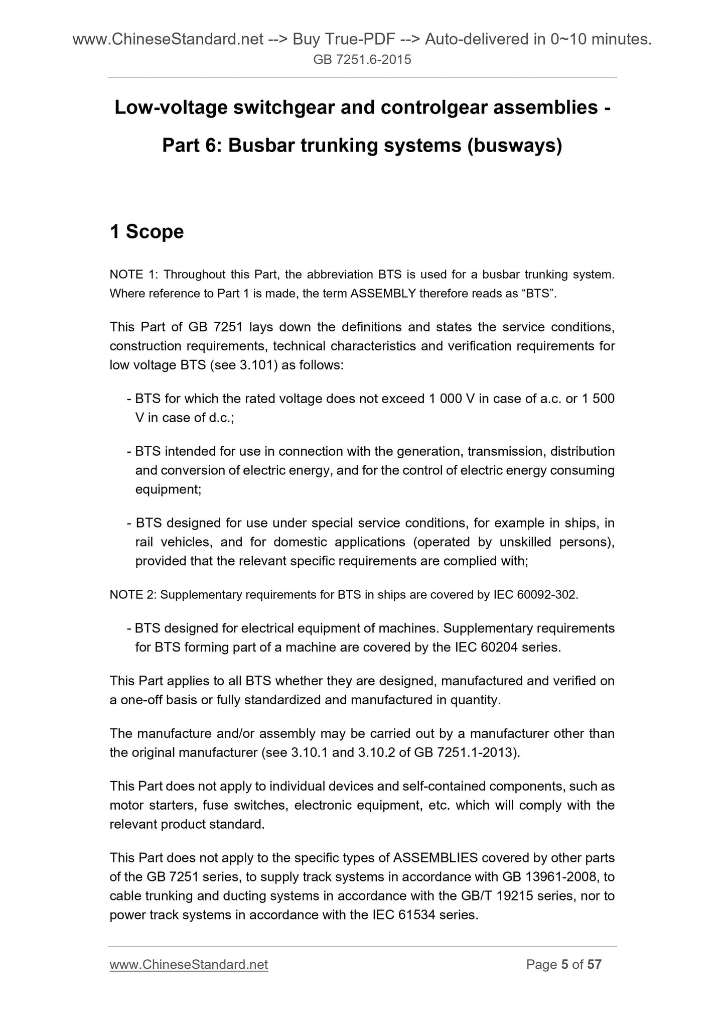
1 Scope
Note 1. Throughout this section, the abbreviation BTS for busbar trunking systems. When it comes to Part 1, the term "equipment" referred to "BTS".
GB 7251 This section specifies the following low-voltage equipment (see 3.101) definition of conditions, construction requirements, technical characteristics and verification
Certification requirements.
--- AC rated voltage not exceeding 1000V, 1500V DC does not exceed the equipment;
--- Equipment and power generation, transmission, distribution, power conversion and control of electric power consumption of the equipment for use;
--- Designed for the special conditions of complete sets of equipment, such as ships, railway and civilian (non-professionals to operate), provided that they meet the relevant special
Statutory requirements;
Note 2. IEC 60092-302 contains marine equipment Supplementary requirements.
--- Equipment for the electrical equipment of machines designed, IEC 60204 contains the complement components constituting the machine complete sets of equipment
Filling requirements.
This section applies to all-time design, manufacture and testing of fully standardized or volume manufacturing equipment.
Production and/or assembly can not the initial manufacturer (see Part 1 3.10.1 and 3.10.2).
This section does not apply to individual devices and self-contained components that conform to their relevant product standards, such as motor starters, fuse open
Off and electronic equipment.
This section does not apply to the rest of 7251 GB in a particular type of equipment, the power rail system GB 13961-2008
EC, GB/T 19215 (all parts) of the cable tray and conduit systems and IEC 61534 (all parts) of a power rail system.
2 Normative references
The following documents for the application of this document is essential. For dated references, only the dated version suitable for use herein
Member. For undated references, the latest edition (including any amendments) applies to this document.
Except as follows, GB 7251.1-2013 of this chapter applies.
increase.
GB 7251.1-2013 Low-voltage switchgear and control equipment Part 1. General (IEC 61439-1.2011, IDT)
GB/T 18380.31-2008 and optical fiber cables under fire conditions test (Part 31). vertically mounted bunched wires
Cable vertical flame spread test test equipment (IEC 60332-3-10.2000, IDT)
IEC 60439-2.2000 Low-voltage switchgear and control equipment Part 2. busbar trunking systems (busways) Special
Requirements [Low-voltageswitchgearandcontrolgearassemblies-Part 2. Particularrequirementsforbusbar
trunkingsystems (busways)]
IEC 61786.1998 on measuring human exposure to low frequency magnetic and electric fields - special equipment requirements and measurement guidelines (Meas-
urementoflow-frequencymagneticandelectricfieldswithregardtoexposureofhumanbeings-Spe-
cialrequirementsforinstrumentsandguidanceformeasurements)
ISO 834-1.1999 Fire resistance tests for structural assemblies - Part 1. General requirements (Fire-resistancetests-
Elementsofbuildingconstruction-Part 1. Generalrequirements)
3 Terms and Definitions
Except as follows, GB 7251.1-2013 of this chapter applies.
Increase definition.
3.101
Busbar trunking system busbartrunkingsystems; BTS
Busway busways
For all types of load distribution and control of electrical energy for industrial, commercial and similar applications, the conductors in the form of a closed system equipment.
The conductor system consists of pipes, grooves or similar enclosure of insulating material spacing and supporting the busbars.
[Source revised IEC 60050-441. 1984,441-12-07]
Note 1. See the definition of equipment GB 7251.1-2013 3.1.1.
Note 2. The busbar trunking system by a series of mechanical and electrical components, such as.
--- With or without busbar trunking unit tap means;
--- Commutation, expansion, bending, feed and variable capacitance unit;
--- Tap unit;
--- For communication and/or control of additional conductors.
Note 3. The term "bus" is not set in advance of the conductor geometry, size and area.
3.102
Busbar trunking unit busbartrunkingunit; BTU
A unit busbar trunking system. The unit consists of bus, bus support and insulation, housing and other fixtures as well as connecting with the unit
Connector connected components. It also means having a tap-tap device may not have.
NOTE. busbar trunking may have different geometric shapes, such as straight, elbow, T-shaped or cross-shaped.
3.103
Busbar trunking channel busbartrunkingrun; BTrun
A plurality of linked units busbar trunking busbar trunking system does not include the tap unit.
3.104
With sub-busbar trunking unit busbartrunkingunitwithtap-offfacilities bonding device; BTUwithtap-offfacili-
ties
By the original manufacturer of pre-fabricated units can be mounted tap busbar trunking unit at one or more points.
3.105
Trolley-style tap busbar trunking unit busbartrunkingunitwithtroley-typetap-offfacilities; BTUwith
troley-typetap-offfacilities
Allow the use of roller-type or trolley-type tap unit busbar trunking units.
3.106
Busbar trunking variable capacitance unit busbartrunkingadapterunit; adapterBTU
The same system is used to connect different models or different rated current of both units of the busbar trunking unit.
3.107
Busbar trunking thermal expansion unit busbartrunkingthermalexpansionunit; thermalexpansionBTU
Allow due to thermal expansion of the busbar trunking system axial channel has a certain amount of movement of the busbar trunking unit.
Note. This term does not default which allow the mobile part, for example. conductor or conductors within the housing and the housing at the same time.
3.108
Busbar trunking commutation unit busbartrunkingphasetranspositionunit; phasetranspositionBTU
For changing the phase conductors are arranged corresponding to the position or change in position of balance of anti-phase (eg. L1-L2-L3-N is converted into N-L3-L2-L1)
The busbar trunking units.
3.109
Busbar trunking bending unit flexblebusbartrunkingunit; flexbleBTU
Conductor and the housing is designed to allow installation into the specified direction of busbar trunking units.
3.110
Busbar trunking feeding unit busbartrunkingfeederunit; feederBTU
Used as incoming unit of busbar trunking units.
Note. The definition of the line unit, see GB 7251.1-2013 3.1.9.
3.111
Tap-tap-offunit unit
Busbar trunking tap unit from the power outlet unit, which can be fixed or mobile.
Note 1. The definition of qualifying units, fixed parts and mobile parts of 3.1.10,3.2.1 see GB 7251.1-2013 and 3.2.2.
Note 2. Plug-tap unit can be manually connected and disconnected a mobile tap unit (see 8.5.2).
3.112
Busbartrunkingunitforbuildingmovements busbar trunking unit for moving the building structure; BTUfor
buildingmovements
It allows building due to thermal expansion, contraction and/or bending movement of the busbar trunking unit.
3.113
Busbar trunking flame baffle unit busbartrunkingfirebarrierunit; firebarrierBTU
Under fire conditions, for within the specified time to prevent flame penetration busbar trunking structures spread unit or a part thereof.
4 Symbols and Abbreviations
Except as follows, GB 7251.1-2013 of this chapter applies.
increase.
Symbols/Abbreviations Terms reg number
Temperature coefficient k1A busbar trunking system 5.3.1
Temperature coefficient k1c circuit 5.3.2
Installation factor k2c circuit 5.3.2
R, X, Z phase conductor and the faulty circuit characteristics 5.101
5 Interface Features
Except as follows, GB 7251.1-2013 of this chapter applies.
5.1 General
instead.
Performance busbar trunking system shall ensure that the connected circuits are compatible rating and installation conditions, and by busbar trunking system manufacturer
5.2 to 5.6 in accordance with the guidelines and 5.101 ~ 5.102 determined will be described.
Specification of a list of information in Appendix C to help users and busbar trunking system manufacturer for this purpose, regardless of whether the user is.
--- Choose performance to meet the requirements and meet the requirements of this part of the catalog; and/or
--- Specific agreements with manufacturers.
Note. Appendix C is also associated with the Article 6 and 7 of the topic.
In some cases, the information provided by the manufacturer busbar trunking system can replace the agreement.
5.2.4 Rated impulse withstand voltage (Uimp) (complete sets of equipment)
Instead of comments.
Note. Unless otherwise specified, in accordance with GB 7251.1-2013 given in Table G.1 overvoltage category Ⅳ (installation class origin) or Ⅲ (distribution circuit level)
Select the rated impulse withstand voltage.
5.3.1 Equipment rated current (InA)
increase.
When the busbar trunking system is not at one end of the channel is provided with a bus trunk line unit (for example. Note. 4 line unit is not installed in the busbar trunking system
End, or more than one incoming unit), rated current shall be agreed upon between the user and manufacturer.
Rated current applied to a specific direction of installation (see 5.3.2). For horizontal busbar trunking system in the short vertical portion (for example, less than
3m length), the impact of the mounting direction is negligible.
Busbar trunking system manufacturer may indicate different air temperature rated current of busbar trunkin...
Share
