Skip to product information
1 of 12

PayPal, credit cards. Download editable-PDF and invoice in 1 second!

GB 7251.1-2013 English PDF

GB 7251.1-2013 English PDF

Regular price $145.00 USD
Regular price Sale price $145.00 USD
Sale Sold out
Shipping calculated at checkout.
Delivery: 3 seconds. Download true-PDF + Invoice.
Newer version: (Replacing this standard) GB/T 7251.1-2023
Get Quotation: Click GB 7251.1-2013 (Self-service in 1-minute)
Historical versions (Master-website): GB/T 7251.1-2023
Preview True-PDF (Reload/Scroll-down if blank)

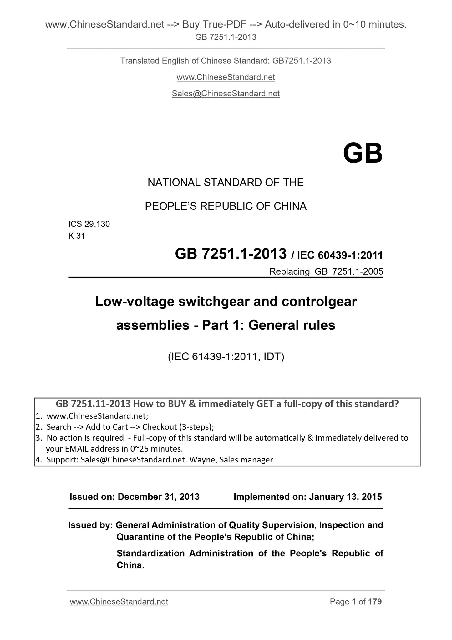
GB 7251.1-2013: [GB/T 7251.1-2013] Low-voltage switchgear and controlgear assemblies -- Part 1: General rules
GB 7251.1-2013
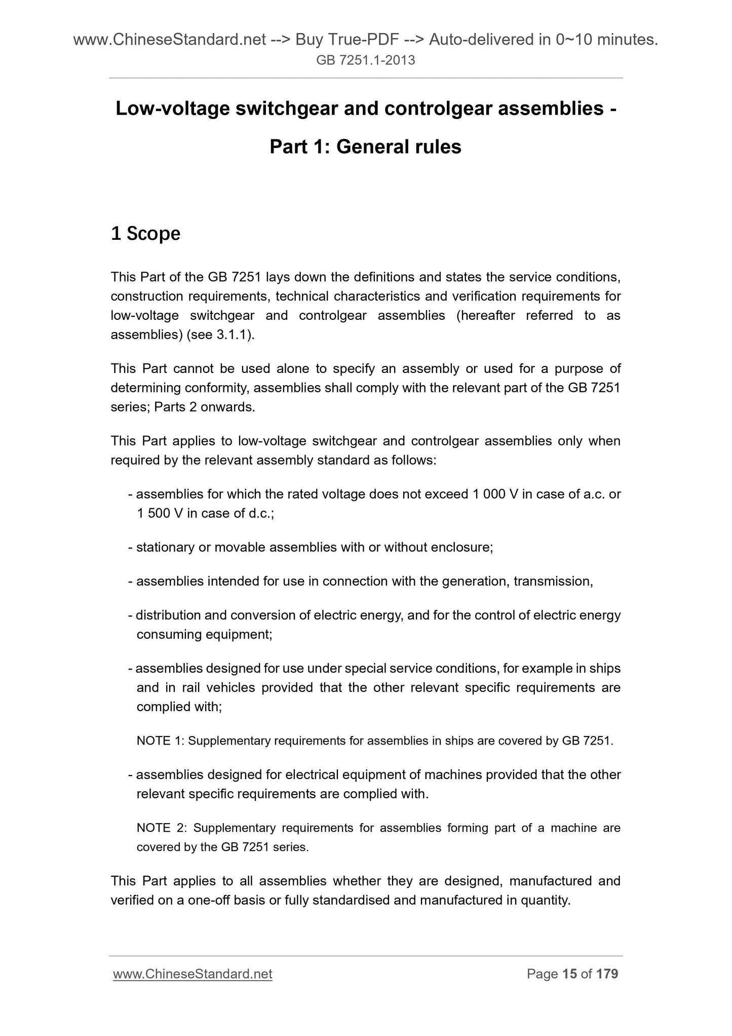
Low-voltage switchgear and controlgear assemblies.Part 1. General rules
ICS 29.130
K31
National Standards of People's Republic of China
Replacing GB 7251.1-2005
Low-voltage switchgear and control equipment
Part 1. General
Part 1. Generalrules
(IEC 61439-1.2011, IDT)
Published 2013-12-31
2015-01-13 implementation
Administration of Quality Supervision, Inspection and Quarantine of People's Republic of China
Standardization Administration of China issued
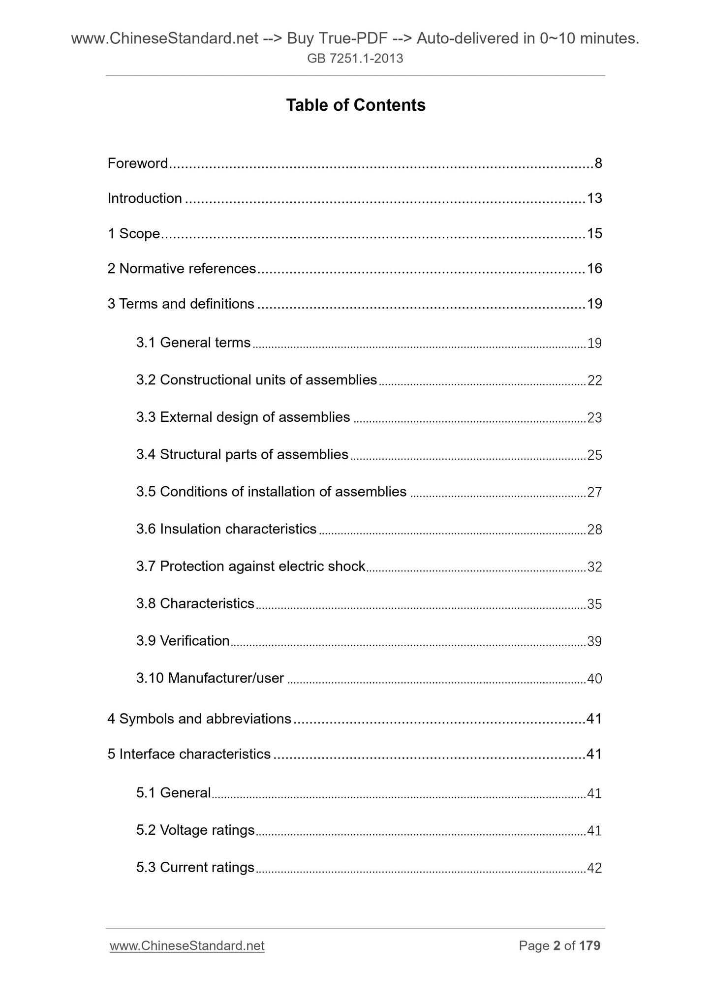
Table of Contents
Preface Ⅶ
Introduction Ⅹ
1 Scope 1
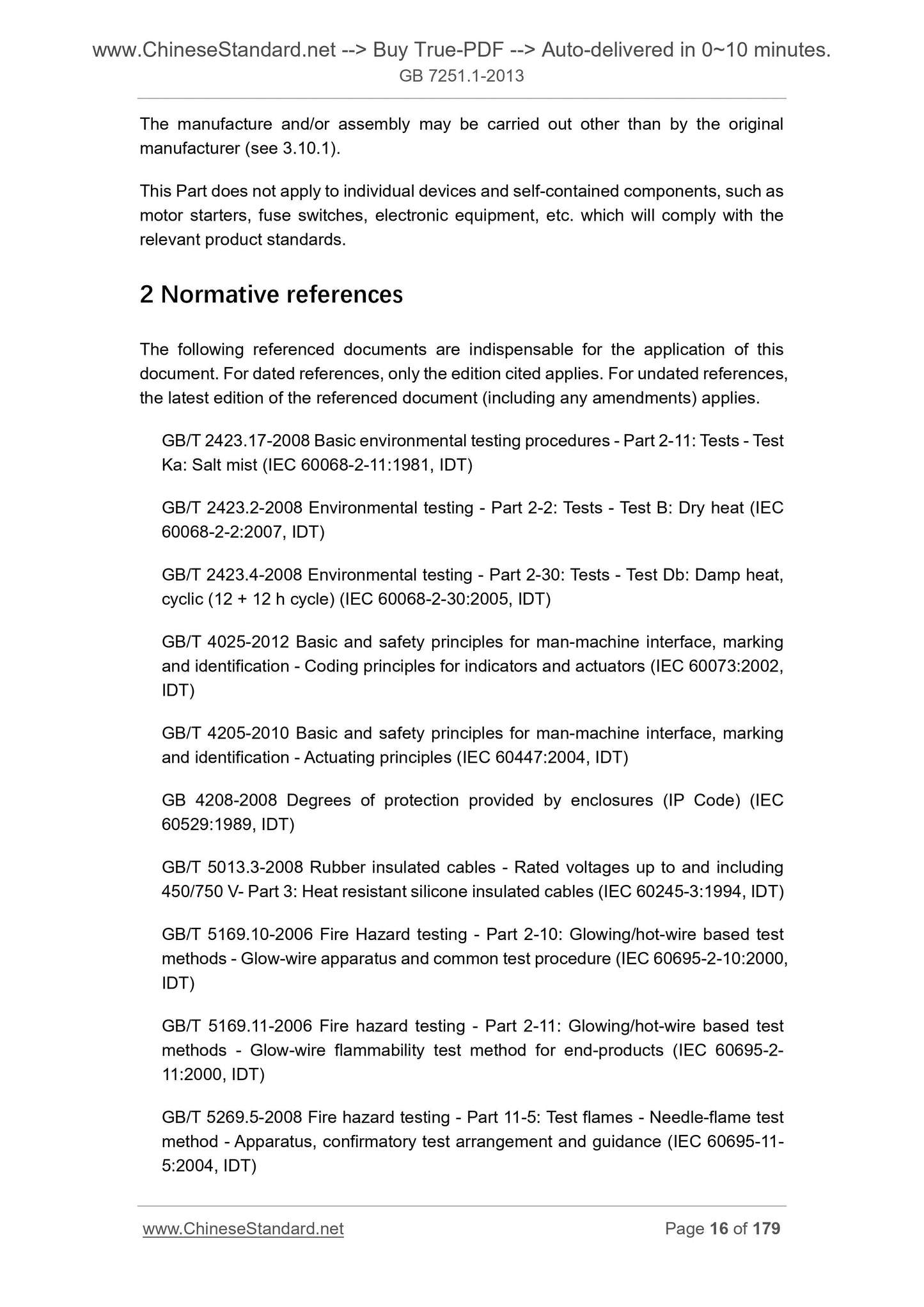
2 Normative References 1
3 Terms and definitions 4
4 3.1 generic term
3.2 Equipment configuration unit 5
Shape design equipment 6 3.3
3.4 Equipment structural member 7
3.5 Equipment mounting condition 8
3.6 insulating properties 8
10 3.7 Protection against electric shock
3.8 Characteristics 12
3.9 Verify 14
3.10 Manufacturer/user 15
Symbols and abbreviations 4 15
5 Interface Features 16
5.1 General 16
5.2 Rated voltage data 16
Current nominal data 16 5.3
5.4 nominal scattering coefficient (RDF) 17
5.5 rated frequency (fn) 17
5.6 Other features 18
6 information 18
Marks under 6.1 Equipment 18
6.2 file 18
6.3 identification devices and/or elements 19
7 Conditions 19
7.1 normal conditions of use 19
20 7.2 Special conditions of use
7.3 Transportation, storage and installation conditions 20
8 structural requirements 21
8.1 Materials and strength member 21
8.2 degree of protection equipment housing 22
8.3 clearances and creepage distances 22
23 8.4 Protection against electric shock
8.5 switching device combination and element 28
8.6, and the internal circuit 29 is connected
8.7 Cooling 31
An external lead terminal 31 8.8
9 Performance requirements 32
32 9.1 Dielectric Properties
9.2 temperature limit 32
9.3 Short-circuit protection and short-circuit withstand strength 33
9.4 Electromagnetic compatibility (EMC) 34
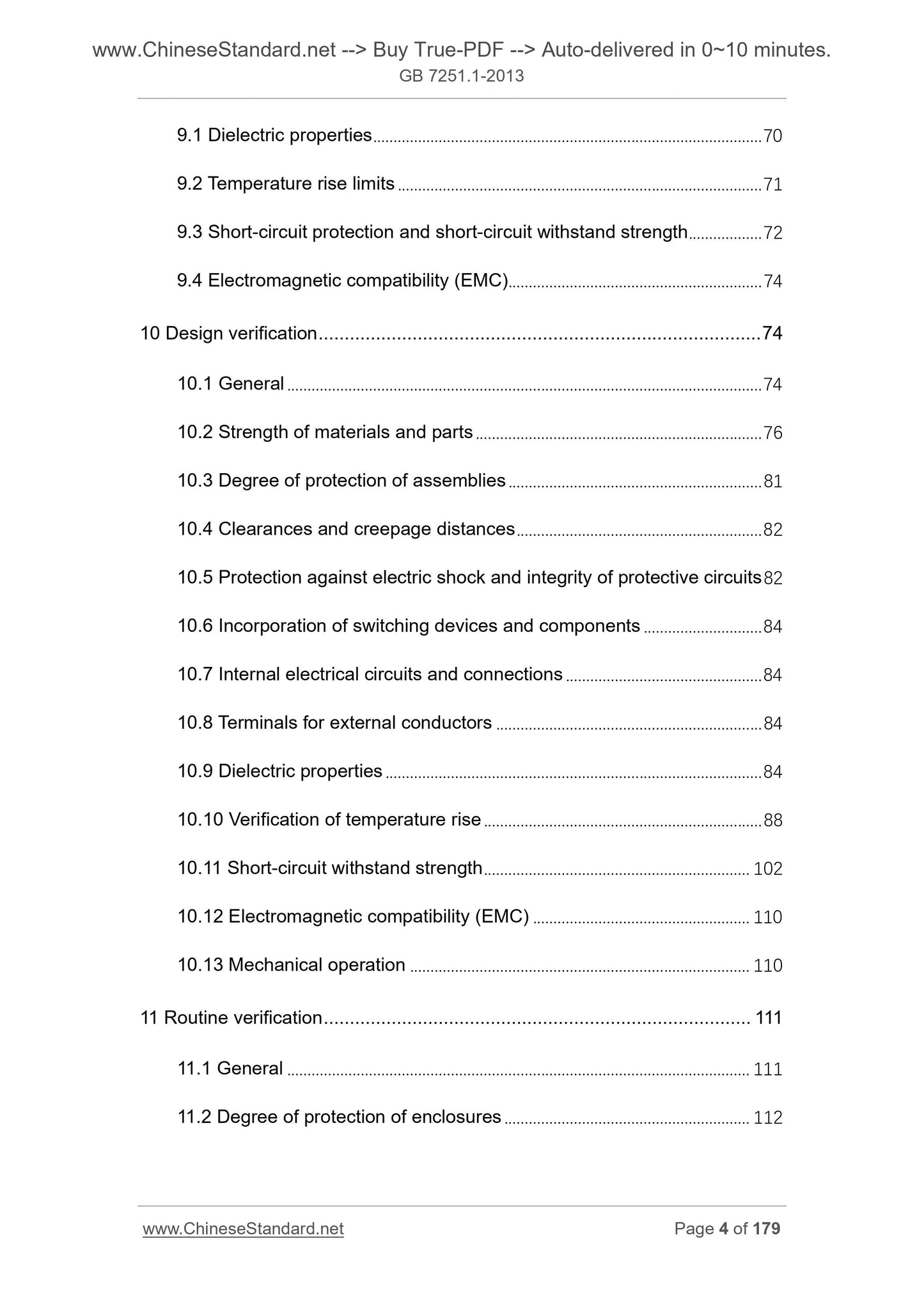
10 34 Design Verification
10.1 General 34
10.2 Materials and strength member 35
Protection level equipment 38 10.3
10.4 clearances and creepage distances 38
10.5 shock protection and integrity protection circuit 38
And combinations of elements of the switching device 10.6 39
Internal circuitry and connections 39 10.7
External lead terminals 39 10.8
10.9 40 Dielectric Properties
10.10 temperature rise verification 42
49 short-circuit withstand strength 10.11
10.12 Electromagnetic compatibility (EMC) 54
10.13 mechanical operation 54
11 54 Routine Tests
11.1 General 54
11.2 the housing 54 degree of protection
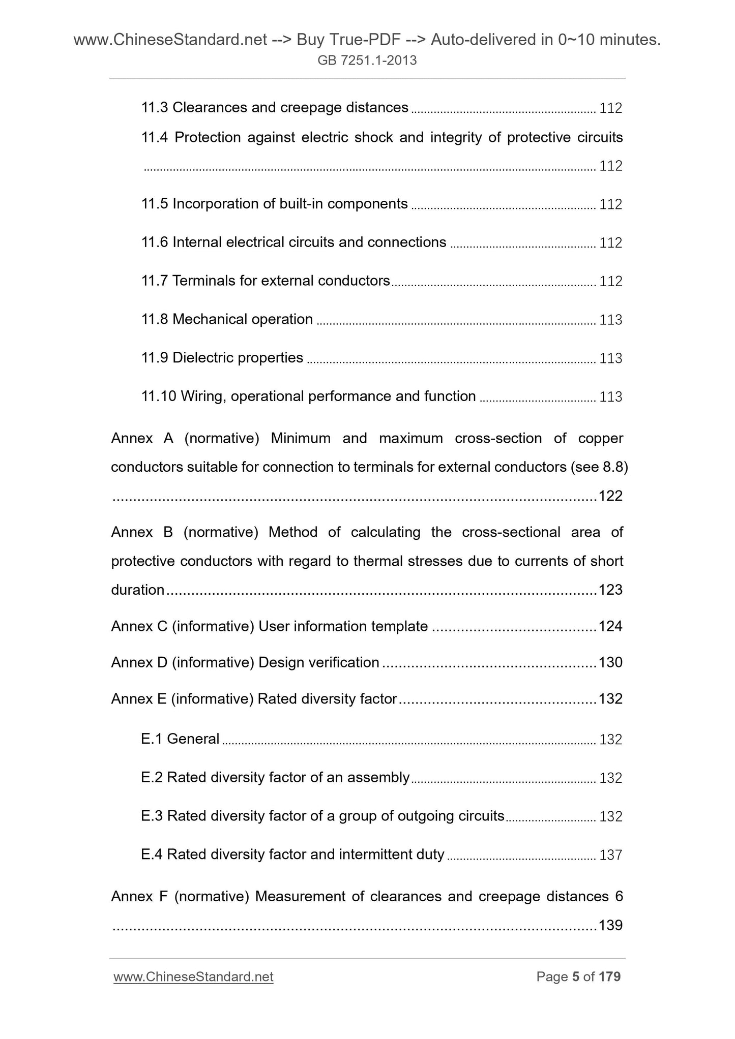
11.3 clearances and creepage distances 55
11.4 Protection against electric shock and protection circuit integrity 55
A combination of elements 55 built 11.5
Internal circuitry and connections 55 11.6
11.7 external lead terminal 55
11.8 mechanical operation 55
11.9 Dielectric properties 55
11.10 wiring, operational performance and functionality 55
Annex A (normative) suitable for connecting the outer conductor terminal with the smallest and largest cross-sectional area of copper wires (see 8.8) 63
Annex B (normative) in short-time current due to thermal stress, the method of calculating the conductor cross-sectional area of protection 64
Annex C (informative) user information template 65
Annex D (informative) design verification 69
Annex E (informative) Rated dispersion coefficient 70
E.1 General 70
E.2 rated equipment scattering coefficient 70
A group of line circuits rated E.3 dispersion coefficient 70
E.4 nominal dispersion coefficient and intermittent duty 74
Measurement Appendix F (normative) clearances and creepage distances 76
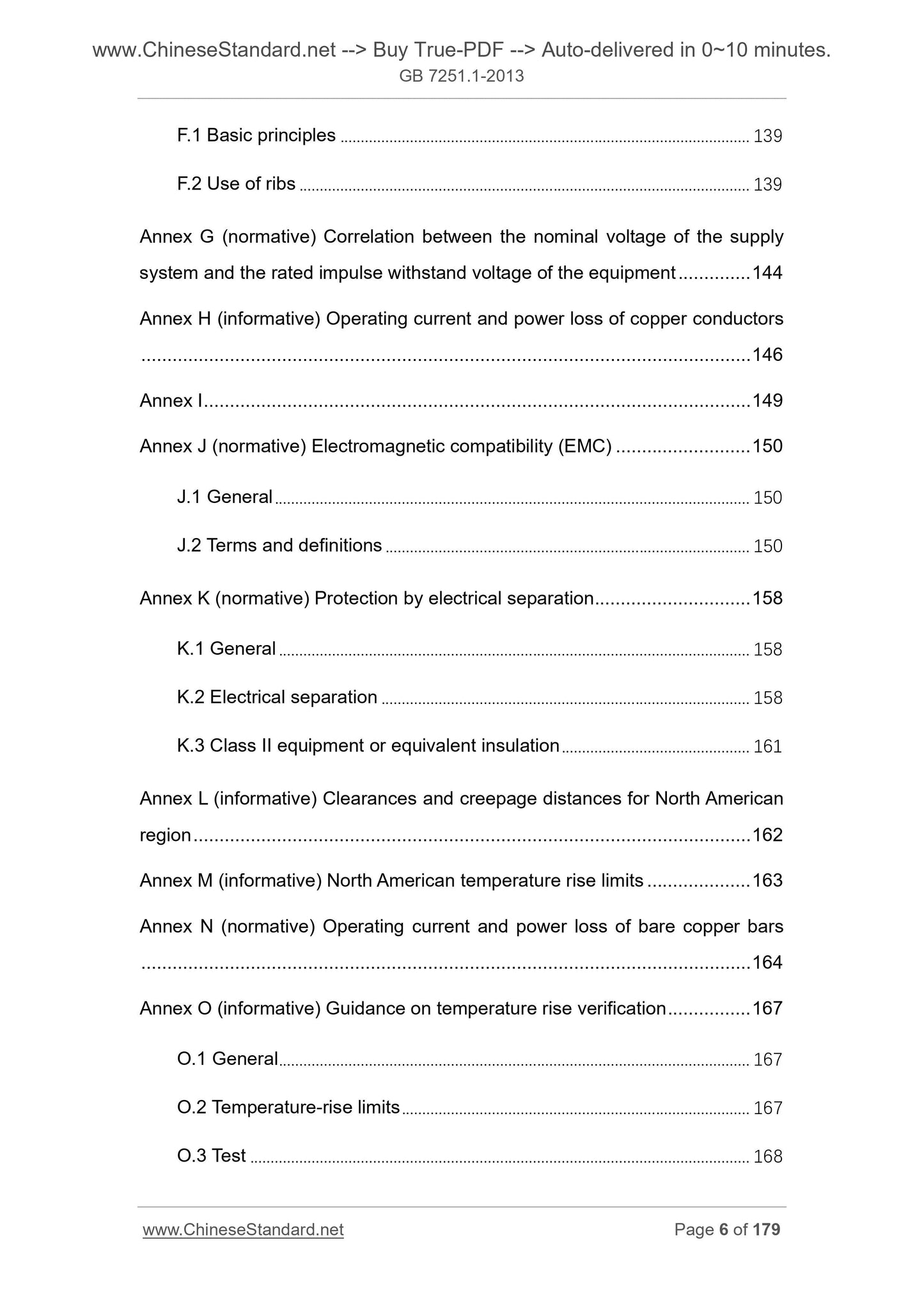
The basic principle F.1 76
F.2 Use of ribs 76
Relationship between nominal voltage rating of the device (normative) Appendix G of the power supply system 81 of the impulse withstand voltage
Annex H (normative) the operating current and power loss of copper wire 82
Appendix I (empty) 84
Annex J (normative) Electromagnetic compatibility (EMC) 85
J.1 General 85
J.2 terms and definitions 85
(Normative) electrical isolation protection Appendix K 90
K.1 General 90
K.2 electrical isolation 90
K.3 Class II or equivalent insulation device 91
Annex L (informative) clearances and creepage distances in North America 92
Annex M (informative) North American temperature rise limit of 93
Annex N (normative) bare copper busbar operating current and power loss 94
Annex O (informative) temperature rise test Guide 96
O.1 General 96
O.2 temperature limit 96
O.3 test 96
Calculation O.4 98
O.5 Design Rule 98
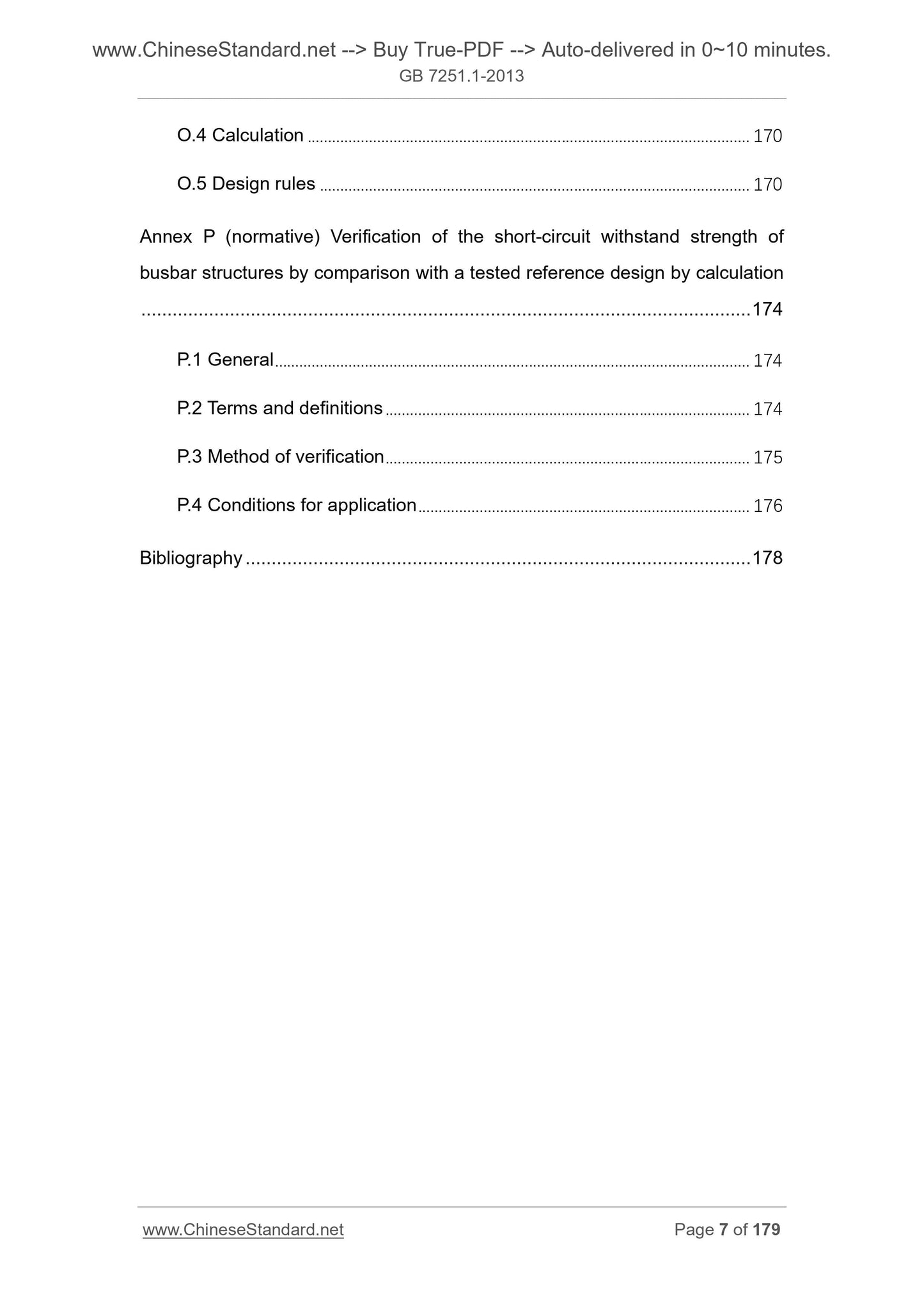
Annex P (normative) verified by calculating the short-circuit withstand strength reference bus configuration design is already tested 100
P.1 General 100
Terms and definitions 100 P.2
P.3 authentication method 101
P.4 application conditions 101
Reference 103
Typical equipment 71 of FIG E.1
Example E.2 Table E.1 FIG polydispersity index of 0.8 the rated equipment load functional unit 172
FIG E.3 Table E.1 rated equipment is an example of the dispersion coefficient of the functional units 272 0.8 load
FIG example E.4 Table E.1 polydispersity index of 0.8 the rated equipment load functional unit 373
FIG E.5 Table E.1 rated equipment is an example of the dispersion coefficient of the functional units 473 0.8 load
Calculating an average thermal effects E.6 Example 74 FIG.
FIG E.7 same RDF and intermittent duty, at t1 = 0.5s, diagram parameters I1 = 7I2 different cycle times Example 75
Parameter relationship diagram when the RDF E.8 same intermittent duty, (not started over current) I1 = I2 Example 75
FIG measured ribs 76 F.1
Example J.1 port 85 of FIG.
FIG temperature authentication method O.1 99
FIG P.1 bus structures have been tested (TS) 100
FIG P.2 untested bus structure (NTS) 101
FIG P.3 corner of a support member 102 of the corner bus bar
Table 1 minimum electrical clearance air in a (8.3.2) 56
Table 2 minimum creepage distance (8.3.3) 56
Table 3 copper protective conductor cross-sectional area (8.4.3.2.2) 57
Table 4 conductor selection and installation requirements (8.6.4) 57
Table 5 Minimum copper protective conductor cross-sectional area (PE, PEN) (8.8) 57
Table 6 temperature limit (9.2) 58
na coefficient values in Table 7 (9.3.3) 59
Table 8 frequency withstand voltage of the main circuit (10.9.2) 59
TABLE auxiliary circuit 9 and the control circuit power frequency voltage withstand value (10.9.2) 59
Table 10 Test impulse withstand voltage (10.9.3) 59
Table 11 for the rated current of 400A with copper wire test (10.10.2.3.2) 60
Table 12 Test for the rated current of copper wires of 400A ~ 4000A (10.10.2.3.2) 61
Table 13 by comparison with a baseline short circuit design verification. checklist (10.5.3.3,10.11.3 and 10.11.4) 61
Table 14 Relationship between the prospective fault current wire diameter 62
Table A.1 copper wire cross-sectional area for connecting the outer conductor terminal 63
Table B.1 k value of the insulation is not included in the protective conductor of the cable, the cable jacket, or the bare protective conductor contact k value 64
Table C.1 Template 65
Table D.1 to be completed design verification list 69
Table E.1 rated polydispersity index of 0.8 to load equipment Example 71
Examples of a group of load circuits (cabinet unit B in FIG E.1) Table E.2 rated polydispersity index of 0.9 to 74
Examples of a group of load circuits (sub-distribution board in Figure E.1) Table E.3 rated polydispersity index of 0.9 to 74
Table F.1 minimum width of the groove 76
Table G.1 nominal voltage power supply system and equipment rated impulse withstand voltage corresponding relationship between the 81
The operating current and power meter at 70 ℃ H.1 allows single core conductor copper cables loss 82
Table H.2 cable conductor temperature derating factor allowing at 70 ℃ k1 83
Table J.1 A class of EMC immunity test environment 88
Table J.2 Class B EMC immunity of the test environment of 88
89 acceptance criteria when electromagnetic disturbances appear in Table J.3
Table K.1 TN system's maximum breaking time of 91
Table L.1 minimum electrical clearance 92 in the air
Table L.2 minimum creepage distance 92
Table M.1 limits of temperature rise in North America 93
Table N.1 bare copper rectangular cross-section of the operating current and power consumption, runs horizontally,
Maximum surface arranged vertically, frequency 50Hz ~ 60Hz 94
Table different air temperature and/or temperature coefficients of the different conductors N.2 equipment k4 95
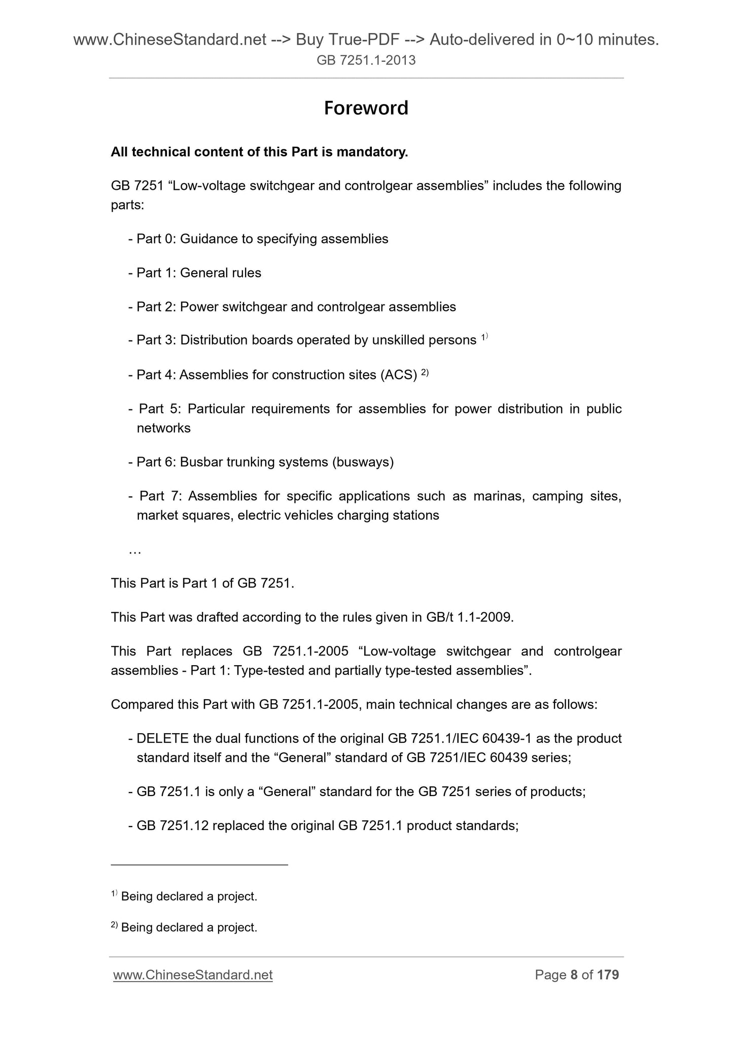
Foreword
All technical contents of this section is mandatory.
GB 7251 "Low-voltage switchgear and control equipment" into the following sections.
--- Part 0. Guide to the provisions of complete sets of equipment
--- Part 1. General
--- Part 2. voltage electrical switching and control device
--- Part 3. Distribution plate 1 operated by a person of ordinary)
--- Part 4. assemblies for construction 2)
--- Part 5. Particular requirements for utility power grid distribution equipment
--- Part 6. busbar trunking systems (busbar)
--- Part 7. --- the particular application equipment such as dock, campsite, Market Square, electric vehicle charging station
1) is being submitted for approval.
2) are being submitted for approval.
This is Part 1 GB 7251's.
This section drafted in accordance with the rules GB/T 1.1-2009 given.
This partial replacement GB 7251.1-2005 "Low-voltage switchgear and control equipment Part 1. Test type test and partially type
Test equipment. "
This section compared with GB 7251.1-2005, the main technical changes are as follows.
--- canceled a GB 7251.1/IEC 60439-1 standard is the product itself, but it is also GB 7251/IEC 60439 series
The "General" standard dual function;
--- GB 7251.1 is only a "General" GB 7251 standards for products;
--- GB 7251.12 replaced the original GB 7251.1 product standards;
--- canceled type test equipment (TTA) by the difference between authentication type testing equipment (PTTA) and a portion;
--- using three different but equivalent forms of verification requirements. i.e. by the verification test, the verification and validation Comparative evaluation;
--- detailed clarify the requirements for temperature rise;
--- detailed description of the nominal scattering coefficient (the RDF);
--- comprising a hollow housing equipment requirements standard (GB/T 20641); and
--- standard throughout its structure as "General" standard to match the new features.
This section uses the translation method is equivalent to using IEC 61439-1.2011 "Low-voltage switchgear and control equipment Part 1. General principles."
Consistency correspondence relationship with international documents in this section of our normative references the following documents.
Identifying GB/T and the basic rules of safety equipment and the conductor terminals of the terminal identification flag HMI 4026-2010
(IEC 60445.2006, IDT)
GB 4824-2004 Industrial Technology, disturbance characteristics medical (ISM) radio equipment limits and measurement methods
(IEC /CISPR11.2003, IDT)
GB/T 5023.3-2008 rated voltage of 450/750V and below PVC insulated cables - Part 3. fixed wiring
Sheathed cable (IEC 60227-3.1997, IDT)
GB/T 5013.4-2008 rated voltage of 450/750V rubber insulated cables and Part 4. Cords and flexible cables
(IEC 60245-4.2004, IDT)
GB/T 6988.1-2008 Preparation of documents used in electrotechnology - Part 1. Rules (IEC 61082-1.2006, IDT)
GB 7251 (all parts) Low-voltage switchgear and control equipment [IEC 60439 (alparts)]
GB/T 9286-1998 Paints and varnishes cut test (ISO 2409.1992, EQV)
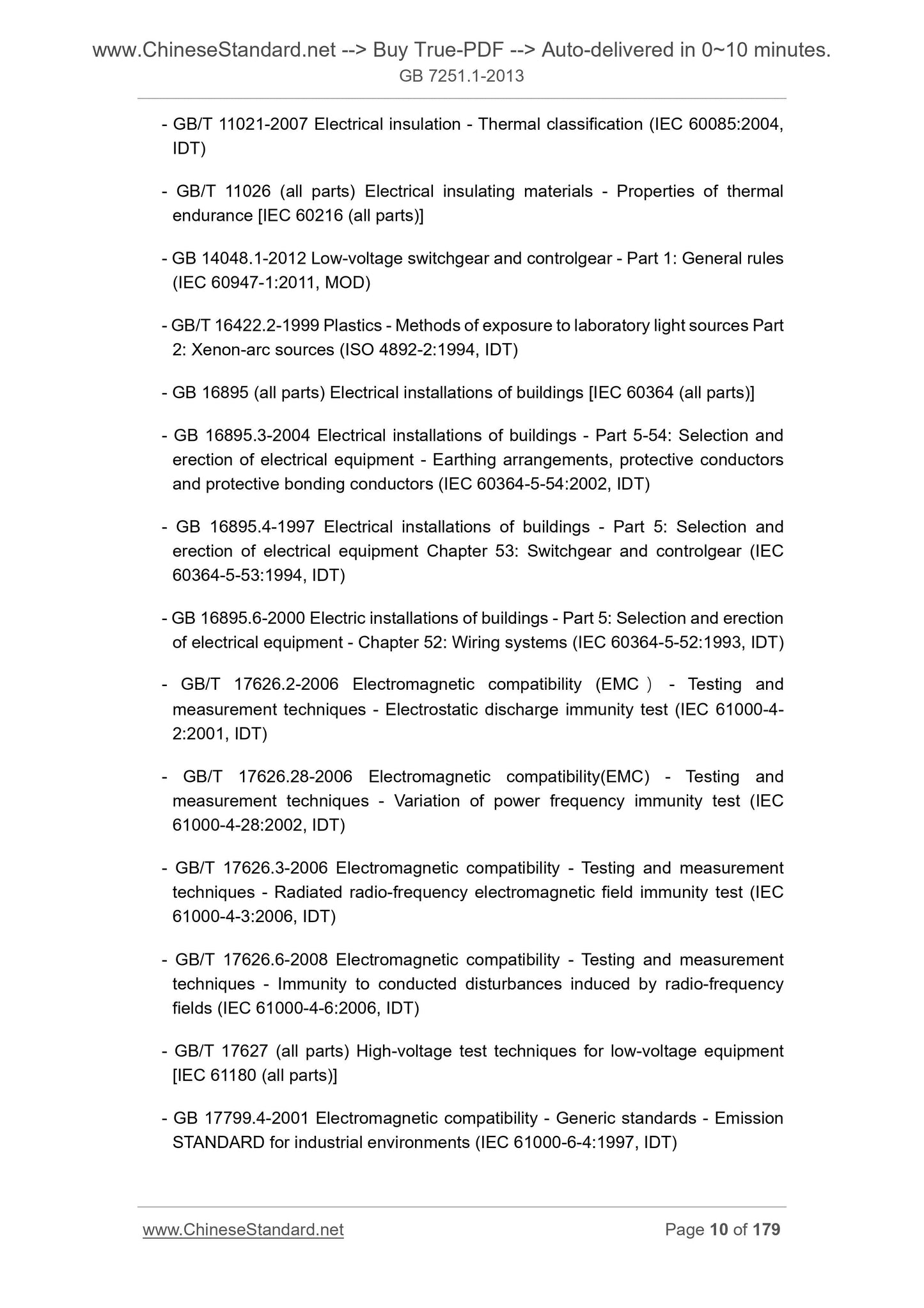
GB/T 11021-2007 heat resistance, electrical insulation classification (IEC 60085.2004, IDT)
GB/T 11026 (all parts) electrically insulating material having heat resistance [IEC 60216 (alparts)]
GB 14048.1-2012 voltage switchgear and control equipment Part 1. General (IEC 60947-1.2011, MOD)
GB/T 16422.2-1999 plastic laboratory light exposure test methods - Part 2. Xenon arc lamp (ISO 4892-2.1994,
IDT)
GB 16895 (all parts) electrical installations of buildings [IEC 60364 (alparts)]
Part 5-54 GB 16895.3-2004 building electrical apparatus. selecting a ground installation and configuration of the electrical equipment, the protective guide
And a protective bonding conductors (IEC 60364-5-54.2002, IDT)
GB 16895.4-1997 Electrical installations of buildings Part 5. Selection and installation of electrical equipment Chapter 53. switching device, and
The control device (IEC 60364-5-53.1994, IDT)
GB 16895.6-2000 Electrical installations of buildings Part 5. Selection and installation of electrical equipment Chapter 52. wiring systems
(IEC 60364-5-52.1993, IDT)
GB/T 17626.2-2006 Electromagnetic compatibility testing and measurement techniques electrostatic discharge immunity test (IEC 61000-4-2.2001,
IDT)
GB/T 17626.28-2006 electromagnetic compatibility test and measurement technology power frequency variations immunity test (IEC 61000-4-
28.2001, IDT)
GB/T 17626.3-2006 Electromagnetic compatibility testing and measurement techniques RFEMS test (IEC 61000-4-
3.2002, IDT)
GB/T 17626.6-2008 Electromagnetic compatibility testing and measurement techniques conducted disturbances induced by radiofrequency fields Immunity (IEC 61000-
4-6.2006, IDT)
High voltage test techniques GB/T 17627 (all parts), low-voltage electrical equipment [IEC 61180 (alparts)]
GB 17799.4-2001 Electromagnetic compatibility - Part 6. Generic standards - Section 4. Emission standard for industrial environments) (IEC 61000-
6-4.1997, IDT)
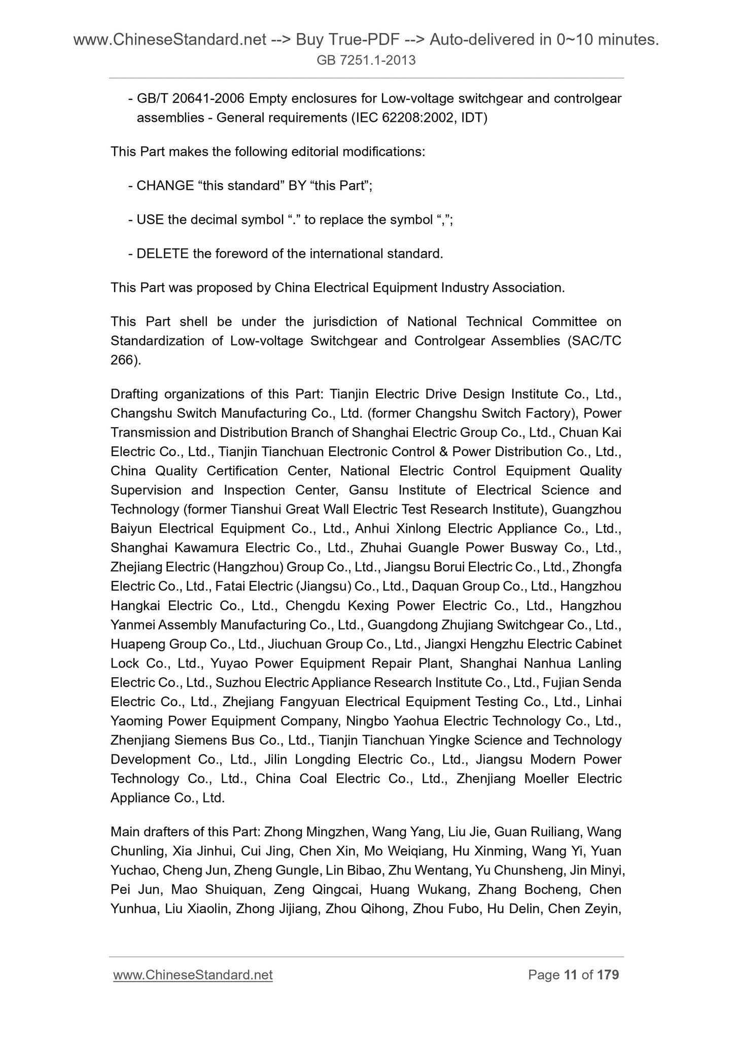
GB/T 20641-2006 General requirements for low voltage switchgear and control equipment shell body (IEC 62208.2002, IDT)
This section made the following editorial changes.
--- "present standard" to "this section";
--- with symbols instead of decimal notation, ",". ",";
--- deleted international standards foreword.
This section was proposed by China Electrical Equipment Industrial Association.
This part is the responsibility of the National Low-voltage switchgear and control...
View full details