www.ChineseStandard.us -- Field Test Asia Pte. Ltd.
GB 5920-2024: Light-signalling devices and systems for motor vehicles and their trailers
Delivery: 9 seconds. Download (and Email) true-PDF + Invoice.
Get Quotation: Click
GB 5920-2024 (Self-service in 1-minute)
Newer / historical versions: GB 5920-2024Preview True-PDF
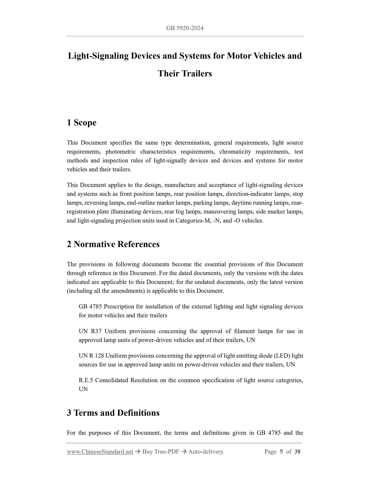
Scope
This Document specifies the same type determination, general requirements, light source
requirements, photometric characteristics requirements, chromaticity requirements, test
methods and inspection rules of light-signally devices and devices and systems for motor
vehicles and their trailers.
This Document applies to the design, manufacture and acceptance of light-signaling devices
and systems such as front position lamps, rear position lamps, direction-indicator lamps, stop
lamps, reversing lamps, end-outline marker lamps, parking lamps, daytime running lamps, rear-
registration plate illuminating devices, rear fog lamps, maneuvering lamps, side marker lamps,
and light-signaling projection units used in Categories-M, -N, and -O vehicles.
Basic Data
| Standard ID | GB 5920-2024 (GB5920-2024) |
| Description (Translated English) | Light-signalling devices and systems for motor vehicles and their trailers |
| Sector / Industry | National Standard |
| Classification of Chinese Standard | T38 |
| Classification of International Standard | 43.040.20 |
| Word Count Estimation | 30,386 |
| Date of Issue | 2024-09-29 |
| Date of Implementation | 2025-07-01 |
| Older Standard (superseded by this standard) | GB 5920-2019,GB 15235-2007,GB 11554-2008,GB 17509-2008,GB 18408-2015,GB 18409-2013,GB 18099-2013,GB 23255-2019 |
| Issuing agency(ies) | State Administration for Market Regulation, China National Standardization Administration |