Skip to product information
1 of 11

www.ChineseStandard.us -- Field Test Asia Pte. Ltd.

GB 55007-2021 English PDF

GB 55007-2021 English PDF

Regular price $710.00
Regular price Sale price $710.00
Sale Sold out
Shipping calculated at checkout.
GB 55007-2021: Code for design of masonry structures
Delivery: 9 seconds. Download (& Email) true-PDF + Invoice.
Get Quotation: Click GB 55007-2021 (Self-service in 1-minute)
Historical versions (Master-website): GB 55007-2021
Preview True-PDF (Reload/Scroll-down if blank)

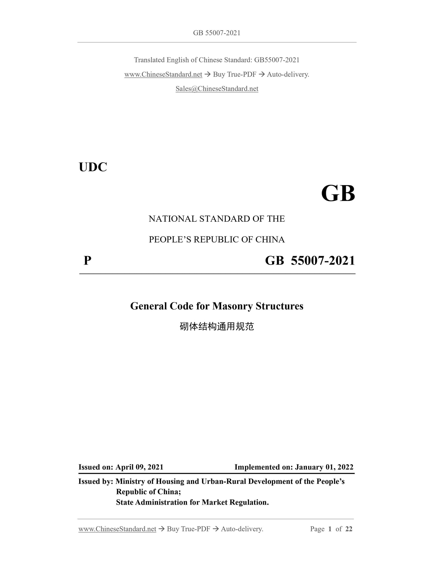
GB 55007-2021
UDC
GB
NATIONAL STANDARD OF THE
PEOPLE’S REPUBLIC OF CHINA
P GB 55007-2021
General Code for Masonry Structures
ISSUED ON: APRIL 09, 2021
IMPLEMENTED ON: JANUARY 01, 2022
Issued by: Ministry of Housing and Urban-Rural Development of the People’s
Republic of China;
State Administration for Market Regulation.
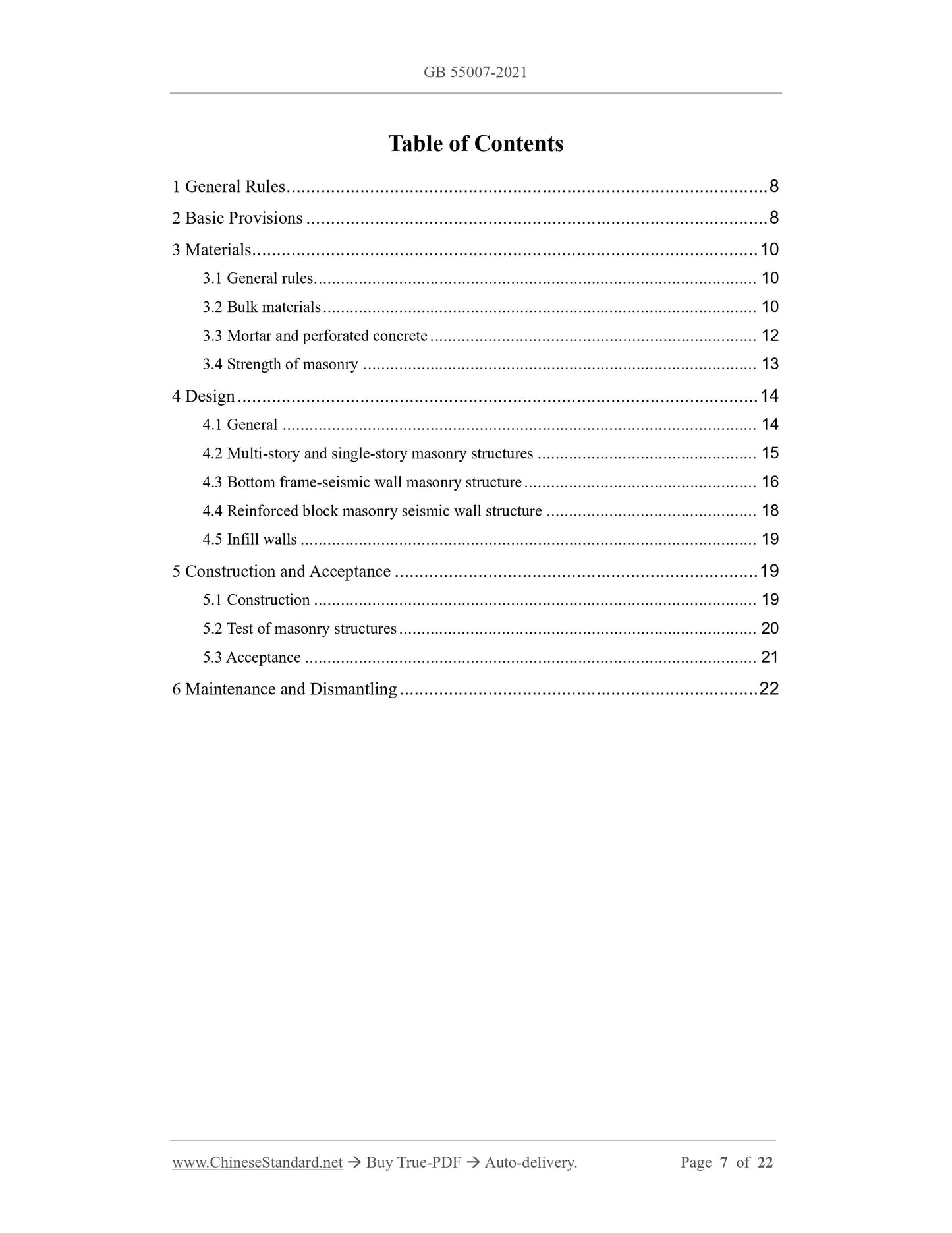
Table of Contents
1 General Rules ... 8
2 Basic Provisions ... 8
3 Materials ... 10
3.1 General rules ... 10
3.2 Bulk materials ... 10
3.3 Mortar and perforated concrete ... 12
3.4 Strength of masonry ... 13
4 Design ... 14
4.1 General ... 14
4.2 Multi-story and single-story masonry structures ... 15
4.3 Bottom frame-seismic wall masonry structure ... 16
4.4 Reinforced block masonry seismic wall structure ... 18
4.5 Infill walls ... 19
5 Construction and Acceptance ... 19
5.1 Construction ... 19
5.2 Test of masonry structures ... 20
5.3 Acceptance ... 21
6 Maintenance and Dismantling ... 22
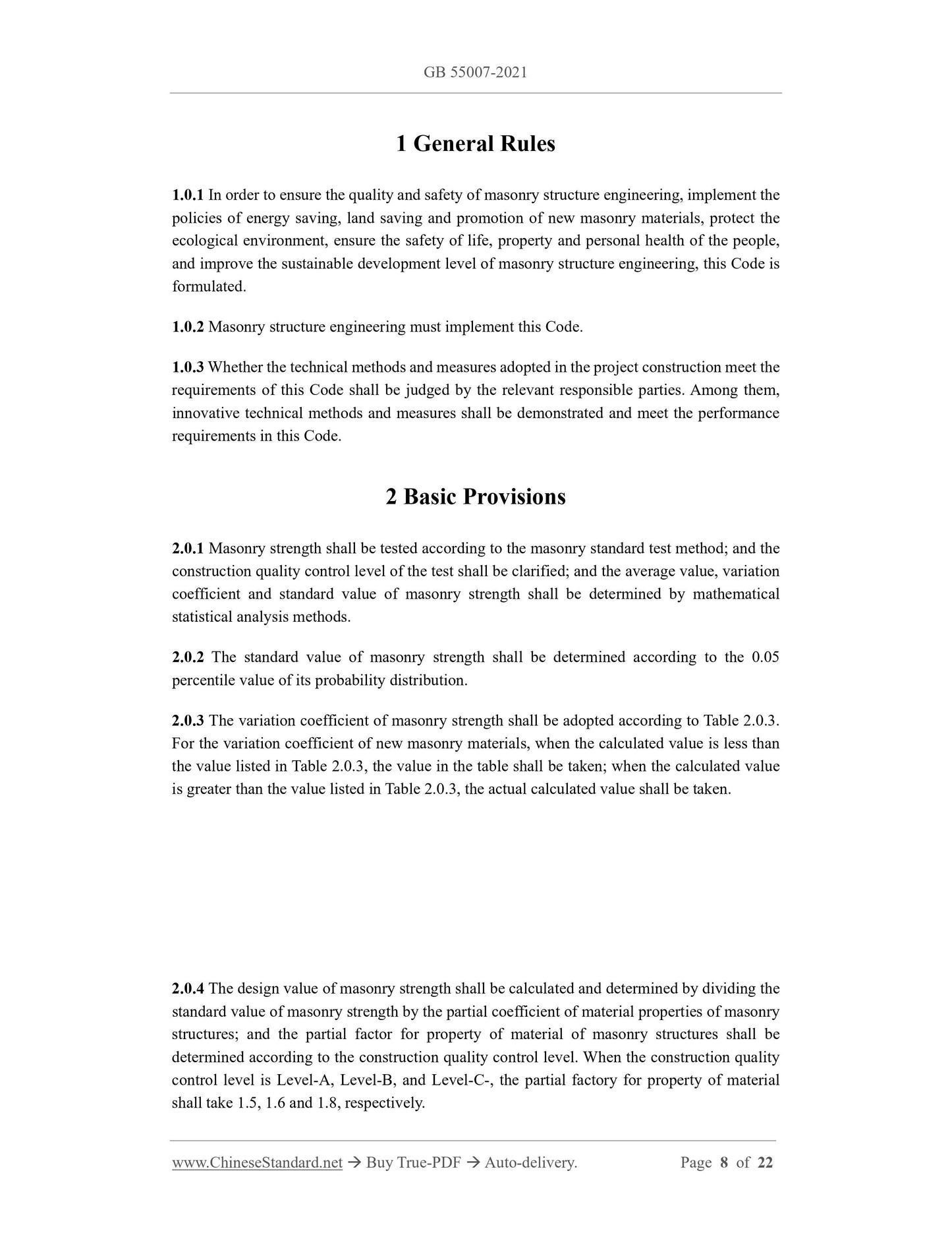
1 General Rules
1.0.1 In order to ensure the quality and safety of masonry structure engineering, implement the
policies of energy saving, land saving and promotion of new masonry materials, protect the
ecological environment, ensure the safety of life, property and personal health of the people,
and improve the sustainable development level of masonry structure engineering, this Code is
formulated.
1.0.2 Masonry structure engineering must implement this Code.
1.0.3 Whether the technical methods and measures adopted in the project construction meet the
requirements of this Code shall be judged by the relevant responsible parties. Among them,
innovative technical methods and measures shall be demonstrated and meet the performance
requirements in this Code.
2 Basic Provisions
2.0.1 Masonry strength shall be tested according to the masonry standard test method; and the
construction quality control level of the test shall be clarified; and the average value, variation
coefficient and standard value of masonry strength shall be determined by mathematical
statistical analysis methods.
2.0.2 The standard value of masonry strength shall be determined according to the 0.05
percentile value of its probability distribution.
2.0.3 The variation coefficient of masonry strength shall be adopted according to Table 2.0.3.
For the variation coefficient of new masonry materials, when the calculated value is less than
the value listed in Table 2.0.3, the value in the table shall be taken; when the calculated value
is greater than the value listed in Table 2.0.3, the actual calculated value shall be taken.
2.0.4 The design value of masonry strength shall be calculated and determined by dividing the
standard value of masonry strength by the partial coefficient of material properties of masonry
structures; and the partial factor for property of material of masonry structures shall be
determined according to the construction quality control level. When the construction quality
control level is Level-A, Level-B, and Level-C-, the partial factory for property of material
shall take 1.5, 1.6 and 1.8, respectively.
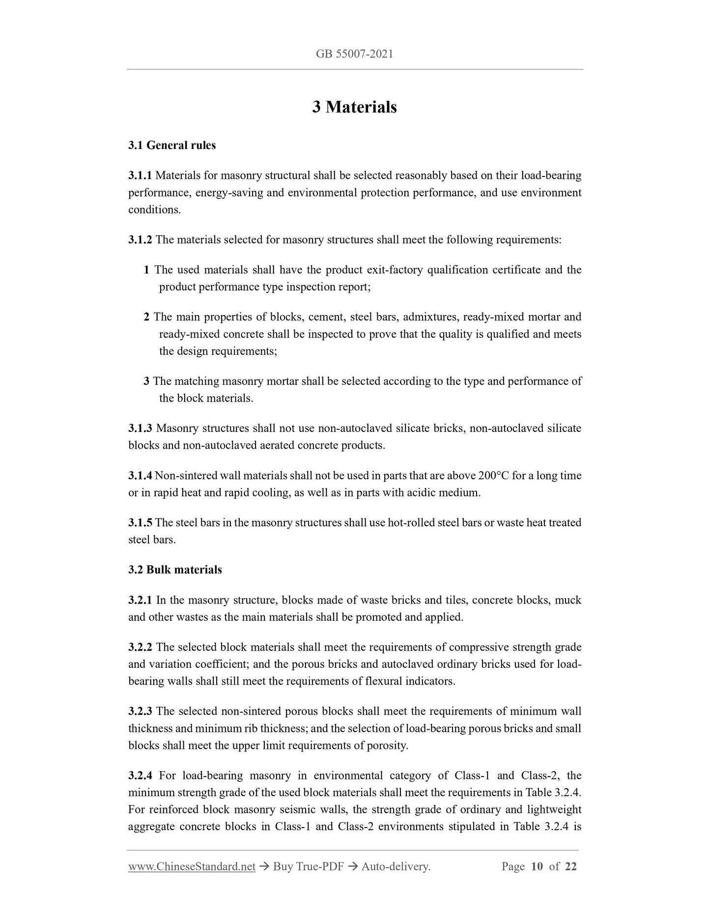
3 Materials
3.1 General rules
3.1.1 Materials for masonry structural shall be selected reasonably based on their load-bearing
performance, energy-saving and environmental protection performance, and use environment
conditions.
3.1.2 The materials selected for masonry structures shall meet the following requirements:
1 The used materials shall have the product exit-factory qualification certificate and the
product performance type inspection report;
2 The main properties of blocks, cement, steel bars, admixtures, ready-mixed mortar and
ready-mixed concrete shall be inspected to prove that the quality is qualified and meets
the design requirements;
3 The matching masonry mortar shall be selected according to the type and performance of
the block materials.
3.1.3 Masonry structures shall not use non-autoclaved silicate bricks, non-autoclaved silicate
blocks and non-autoclaved aerated concrete products.
3.1.4 Non-sintered wall materials shall not be used in parts that are above 200°C for a long time
or in rapid heat and rapid cooling, as well as in parts with acidic medium.
3.1.5 The steel bars in the masonry structures shall use hot-rolled steel bars or waste heat treated
steel bars.
3.2 Bulk materials
3.2.1 In the masonry structure, blocks made of waste bricks and tiles, concrete blocks, muck
and other wastes as the main materials shall be promoted and applied.
3.2.2 The selected block materials shall meet the requirements of compressive strength grade
and variation coefficient; and the porous bricks and autoclaved ordinary bricks used for load-
bearing walls shall still meet the requirements of flexural indicators.
3.2.3 The selected non-sintered porous blocks shall meet the requirements of minimum wall
thickness and minimum rib thickness; and the selection of load-bearing porous bricks and small
blocks shall meet the upper limit requirements of porosity.
3.2.4 For load-bearing masonry in environmental category of Class-1 and Class-2, the
minimum strength grade of the used block materials shall meet the requirements in Table 3.2.4.
For reinforced block masonry seismic walls, the strength grade of ordinary and lightweight
aggregate concrete blocks in Class-1 and Class-2 environments stipulated in Table 3.2.4 is
3.2.9 Lightweight aggregate concrete small hollow blocks or autoclaved aerated concrete
blocks shall not be used for infill walls in the following positions or environments:
1 The wall below the moisture-proof layer of the building (structure);
2 Long-term water immersion or chemical erosion environment;
3 The part where the surface temperature of the masonry is higher than 80℃;
4 Walls that have been in an environment with vibration sources for a long time.
3.3 Mortar and perforated concrete
3.3.1 The minimum strength grade of masonry mortar shall meet the following requirements:
1 The sintered ordinary brick and sintered porous brick masonry with a design service life
greater than or equal to 25 years shall be M5; while the sintered ordinary brick and
sintered porous brick masonry with a design service life of less than 25 years shall be
M2.5;
2 The autoclaved aerated concrete block masonry shall be Ma5; while the autoclaved lime-
sand ordinary brick and autoclaved fly ash ordinary brick masonry shall be Ms5;
3 Concrete ordinary bricks and concrete porous brick masonry shall be Mb5;
4 Concrete block and gangue concrete block masonry shall be Mb7.5;
5 Reinforced block masonry shall be Mb10;
6 The rubble stone and rubble masonry shall be M5.
3.3.2 The perforated concrete strength grade of the concrete block masonry shall be no lower
than Cb20; and shall be no lower than 1.5 times the strength grade of the block.
3.3.3 When designing masonry with frost resistance requirements, the mortar shall be subjected
to freeze-thaw test, and its frost resistance performance shall be no lower than that of wall
blocks.
3.3.4 The masonry with reinforced bars shall not use mortar mixed with chlorine salt and sulfate
admixtures.
3.3.5 The material selection of reinforced block masonry shall meet the following requirements:
1 The perforated concrete shall have shrinkage resistance;
2 For reinforced block masonry buildings with a safety grade of Class I or a design service
life greater than 50 years, the minimum strength grade of mortar and perforated concrete
shall be increased by at least one grade in accordance with the relevant provisions of this
value of the compressive strength of non-perforated masonry.
4 Design
4.1 General
4.1.1 The masonry structure shall be designed according to the limit state of bearing
capacity; and structural measures shall be taken according to the characteristics of the
masonry structure to meet the requirements of the limit state of normal service and
durability.
4.1.2 The masonry structural members shall, according to their stress, calculate the bearing
capacity such as axial compression, eccentric compression, local compression, bending
and shearing, etc.; and the members shall be ensured to have sufficient strength to meet
safety requirements.
4.1.3 Various wall and column members of masonry structure shall be checked for height-
thickness ratio to ensure member stability.
4.1.4 For unreinforced masonry compression members, the axial force eccentricity e
calculated according to the design value of internal force shall be no greater than 0.6y; y
is the distance from the center of gravity of the section to the edge of the section in the
eccentric direction where the axial force is located.
4.1.5 The corner of the wall and the junction of the longitudinal and horizontal walls shall
be provided with horizontal tie reinforcement or welded reinforcement mesh.
4.1.6 Reinforced concrete floors and roof panels shall meet the following requirements:
1 The length of the cast-in-place reinforced concrete floor or roof slab extending into the
longitudinal and transverse walls shall be no less than 120mm;
2 The supporting length of the prefabricated reinforced concrete slab on the concrete beam
or ring beam shall be no less than 80mm. When the slab is not placed directly on the ring
beam, the supporting length on the inner wall shall be no less than 100mm; and the
supporting length on the outer wall shall be no less than 120mm;
3 The steel bar at the end of the prefabricated reinforced concrete slab shall be bound to the
longitudinal reinforcement arranged along the wall or ring beam at the support; and the
concrete with a strength grade of no less than C25 shall be used to form a slab strip;
4 When the prefabricated reinforced concrete slab is docked with the cast-in-place slab, the
steel bars at the end of the prefabricated slab shall be reliably connected to the cast-in-
place slab;
5 When the span of the prefabricated reinforced concrete slab is greater than 4.8m and
parallel to the outer wall, the side of the prefabricated slab close to the outer wall shall
be tied to the wall or ring beam;
6 Reinforced concrete prefabricated slabs shall be tied to each other and to beams, walls or
ring beams.
4.1.7 Brick chimney blocks shall be made of sintered ordinary bricks, and the height shall
be no greater than 60m. Brick chimneys shall not be used for Class- III and IV sites with
seismic fortification intensity of 8 degrees, and for seismic fortification intensity of 9
degrees.
4.2 Multi-story and single-story masonry structures
4.2.1 The single-story masonry structure bearing the crane load shall adopt reinforced
masonry structure.
4.2.2 For the load-bearing structure of the hall roof of a single-story open house, brick
columns shall not be used in the following cases:
1 There is a cantilever platform in the hall;
2 For intensity of 6 degrees, the span of the hall is greater than 15m or the height of the
column top is greater than 8m;
3 For intensity of 7 degrees (0.1g), the span of the hall is greater than 12m or the height of
the column top is greater than 6m;
4 Halls with intensity of 7 degrees (0.15g), 8 degrees, and 9 degrees.
4.2.3 Unreinforced masonry members shall not be used for load-bearing wall beams in
multi-story masonry structure buildings to support. The wall beam design shall include the
structural requirements of the total height of the wall, span, height-span ratio of the wall
and joist, opening size and opening position.
4.2.4 For civil buildings with multi-story masonry structure, when the number of stories
is 3 or 4, a ring beam shall be set at the ground floor and cornice elevation, respectively.
When the number of stories exceeds 4, in addition to setting a ring beam at the ground
floor and cornice elevations, respectively; at least all longitudinal and transverse walls
shall be provided with partitions. For multi-story masonry industrial buildings, ring beams
shall be set on each story. For a multi-story masonry structure building with wall beams,
ring beams shall be set at the joist beams, the top surface of the wall beams and the cornice
elevation.
4.2.5 For empty single-story buildings such as factory buildings, warehouses, and canteens,
ring beams shall be set according to the following provisions:
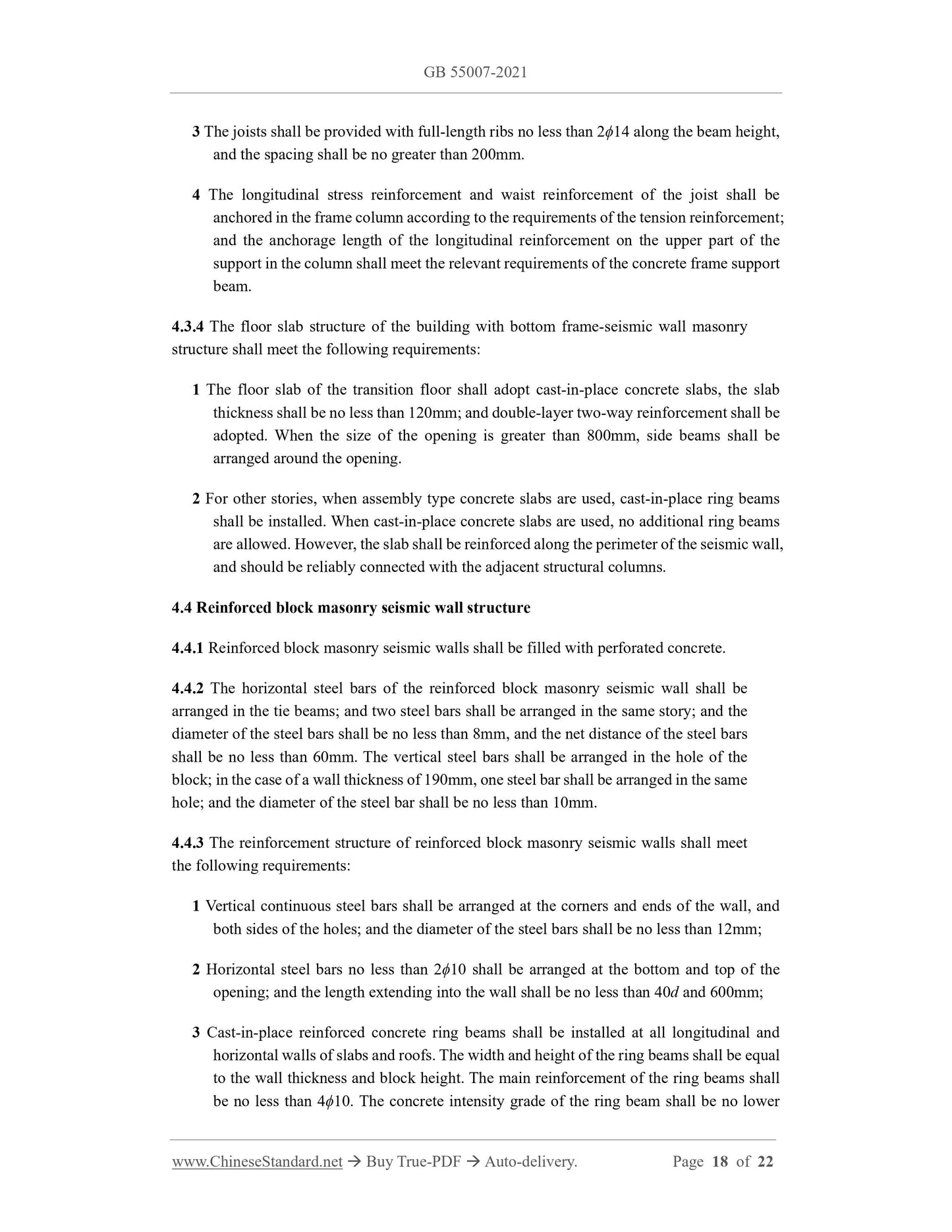
4 When masonry seismic walls are adopted, core columns or concrete structural columns
shall be arranged on both sides of the opening; when the wall length is greater than 4m,
core columns or concrete structural columns shall be arranged in the middle of the wall.
4.3.2 The frame columns at the bottom of a bottom frame-seismic wall masonry structure
building shall meet the following requirements:
1 The section size of the frame column shall be no less than 400mm×400mm; and the
diameter of the cylinder shall be no less than 450mm.
2 The axial compression ratio of the frame column shall be no greater than 0.85 in area with
intensity of 6 degrees, no greater than 0.75 in area with intensity of 7 degrees, and no
greater than 0.65 in area with intensity of 8 degrees.
3 For the minimum total reinforcement ratio of the longitudinal reinforcement of the frame
column, when the strength standard value of the reinforcement is lower than 400MPa, it
shall be no less than 0.9% when the central column is in the areas with intensity of 6
degrees and 7 degrees; and shall be no less than 1.1% when in area with intensity of 8
degrees. It shall be no less than 1.0% when angle columns, side columns, and end
columns of concrete seismic wall are in areas with intensity of 6 degrees and 7 degrees;
and shall be no less than 1.2% when in area with intensity of 8 degrees.
4 The stirrup diameter of the frame column shall be no less than 8mm in the areas with
intensity of 6 degrees and 7 degrees; and shall be less than 10mm in area with intensity
of 8 degrees. And the stirrup shall be densely packed at the full height; and the stirrup
spacing shall be no greater than 100mm.
5 The combined bending moment design value of the uppermost end and the lowermost end
of the frame column shall be multiplied by t...
View full details