Skip to product information
1 of 12

PayPal, credit cards. Download editable-PDF and invoice in 1 second!

GB 50211-2014 English PDF

GB 50211-2014 English PDF

Regular price $2,605.00 USD
Regular price Sale price $2,605.00 USD
Sale Sold out
Shipping calculated at checkout.
Delivery: 3 seconds. Download true-PDF + Invoice.
Get Quotation: Click GB 50211-2014 (Self-service in 1-minute)
Historical versions (Master-website): GB 50211-2014
Preview True-PDF (Reload/Scroll-down if blank)

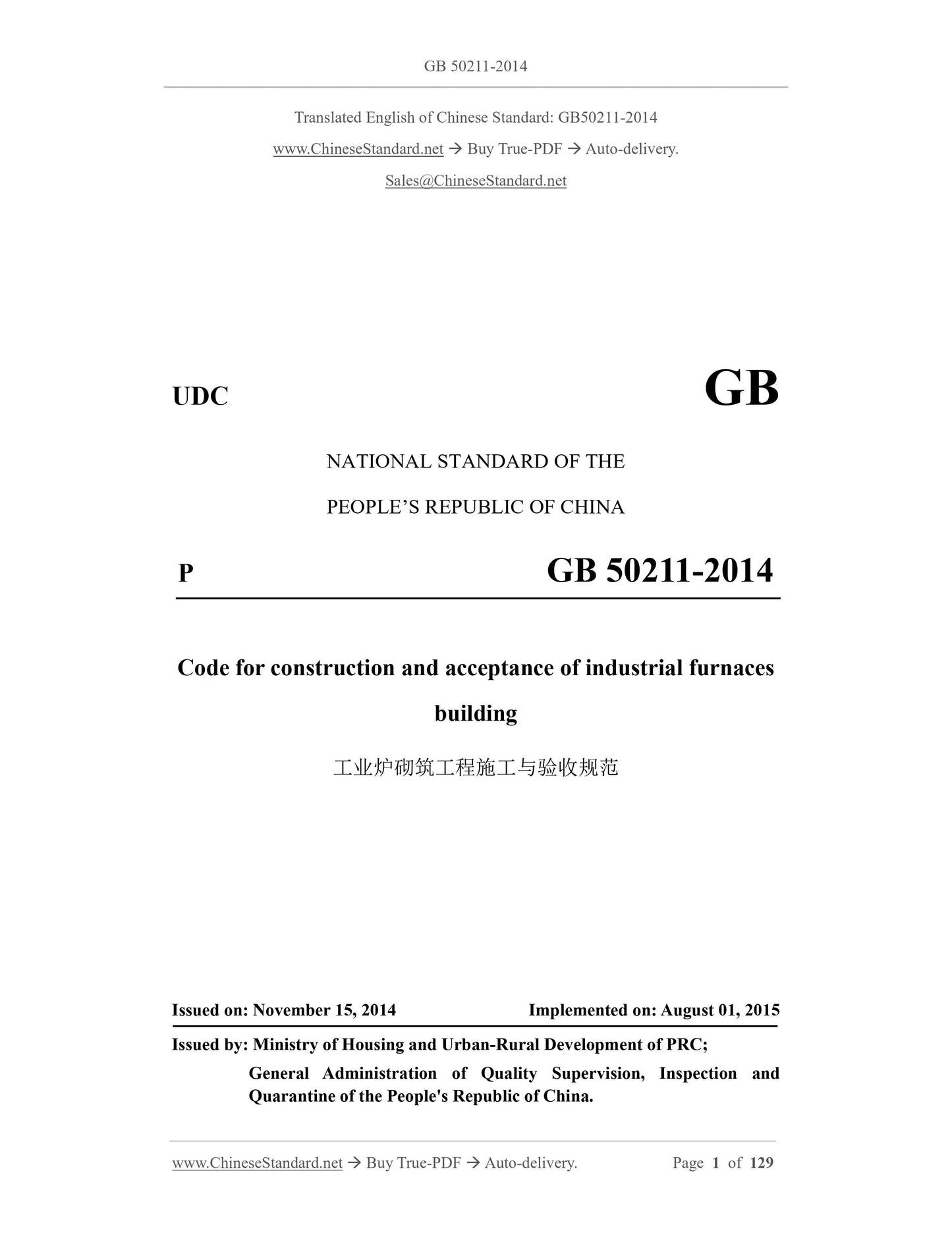
GB 50211-2014: Code for construction and acceptance of industrial furnaces building
GB 50211-2014
UDC GB
NATIONAL STANDARD OF THE
PEOPLE’S REPUBLIC OF CHINA
P GB 50211-2014
Code for construction and acceptance of industrial furnaces
building
ISSUED ON: NOVEMBER 15, 2014
IMPLEMENTED ON: AUGUST 01, 2015
Issued by: Ministry of Housing and Urban-Rural Development of PRC;
General Administration of Quality Supervision, Inspection and
Quarantine of the People's Republic of China.
Table of Contents
Foreword ... 7
1 General provisions ... 11
2 Terms ... 11
3 Basic requirements ... 13
3.1 Acceptance, storage and transportation of materials ... 13
3.2 Construction ... 14
4 Unshaped refractories ... 24
4.1 General requirements ... 24
4.2 Refractory mortar ... 25
4.3 Castable refractories ... 26
4.4 Plastic refractories ... 29
4.5 Ramming refractories ... 31
4.6 Spraying refractories ... 32
4.7 Injection refractories ... 33
5 Refractory ceramic fiber ... 34
5.1 General requirements ... 34
5.2 Layer lining ... 35
5.3 Stacked lining ... 37
5.4 Foldable module ... 38
6 Blast furnace and accessory equipment ... 40
6.1 General requirements ... 40
6.2 Blast furnace ... 44
6.3 Hot stove ... 47
6.4 Hot blast pipe ... 50
7 Coke oven and dry quenching equipment ... 51
7.1 Coke oven ... 51
7.2 Coke dry quenching equipment ... 57
8 Steelmaking furnaces and associated equipment ... 62
8.1 General requirements ... 62
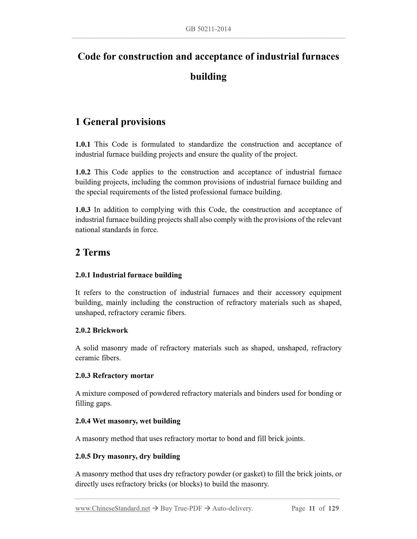
Code for construction and acceptance of industrial furnaces
building
1 General provisions
1.0.1 This Code is formulated to standardize the construction and acceptance of
industrial furnace building projects and ensure the quality of the project.
1.0.2 This Code applies to the construction and acceptance of industrial furnace
building projects, including the common provisions of industrial furnace building and
the special requirements of the listed professional furnace building.
1.0.3 In addition to complying with this Code, the construction and acceptance of
industrial furnace building projects shall also comply with the provisions of the relevant
national standards in force.
2 Terms
2.0.1 Industrial furnace building
It refers to the construction of industrial furnaces and their accessory equipment
building, mainly including the construction of refractory materials such as shaped,
unshaped, refractory ceramic fibers.
2.0.2 Brickwork
A solid masonry made of refractory materials such as shaped, unshaped, refractory
ceramic fibers.
2.0.3 Refractory mortar
A mixture composed of powdered refractory materials and binders used for bonding or
filling gaps.
2.0.4 Wet masonry, wet building
A masonry method that uses refractory mortar to bond and fill brick joints.
2.0.5 Dry masonry, dry building
A masonry method that uses dry refractory powder (or gasket) to fill the brick joints, or
directly uses refractory bricks (or blocks) to build the masonry.
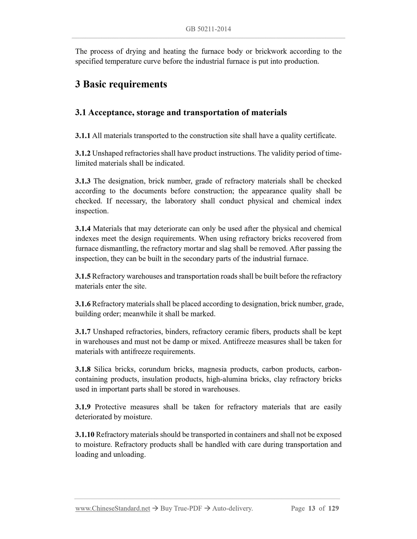
The process of drying and heating the furnace body or brickwork according to the
specified temperature curve before the industrial furnace is put into production.
3 Basic requirements
3.1 Acceptance, storage and transportation of materials
3.1.1 All materials transported to the construction site shall have a quality certificate.
3.1.2 Unshaped refractories shall have product instructions. The validity period of time-
limited materials shall be indicated.
3.1.3 The designation, brick number, grade of refractory materials shall be checked
according to the documents before construction; the appearance quality shall be
checked. If necessary, the laboratory shall conduct physical and chemical index
inspection.
3.1.4 Materials that may deteriorate can only be used after the physical and chemical
indexes meet the design requirements. When using refractory bricks recovered from
furnace dismantling, the refractory mortar and slag shall be removed. After passing the
inspection, they can be built in the secondary parts of the industrial furnace.
3.1.5 Refractory warehouses and transportation roads shall be built before the refractory
materials enter the site.
3.1.6 Refractory materials shall be placed according to designation, brick number, grade,
building order; meanwhile it shall be marked.
3.1.7 Unshaped refractories, binders, refractory ceramic fibers, products shall be kept
in warehouses and must not be damp or mixed. Antifreeze measures shall be taken for
materials with antifreeze requirements.
3.1.8 Silica bricks, corundum bricks, magnesia products, carbon products, carbon-
containing products, insulation products, high-alumina bricks, clay refractory bricks
used in important parts shall be stored in warehouses.
3.1.9 Protective measures shall be taken for refractory materials that are easily
deteriorated by moisture.
3.1.10 Refractory materials should be transported in containers and shall not be exposed
to moisture. Refractory products shall be handled with care during transportation and
loading and unloading.
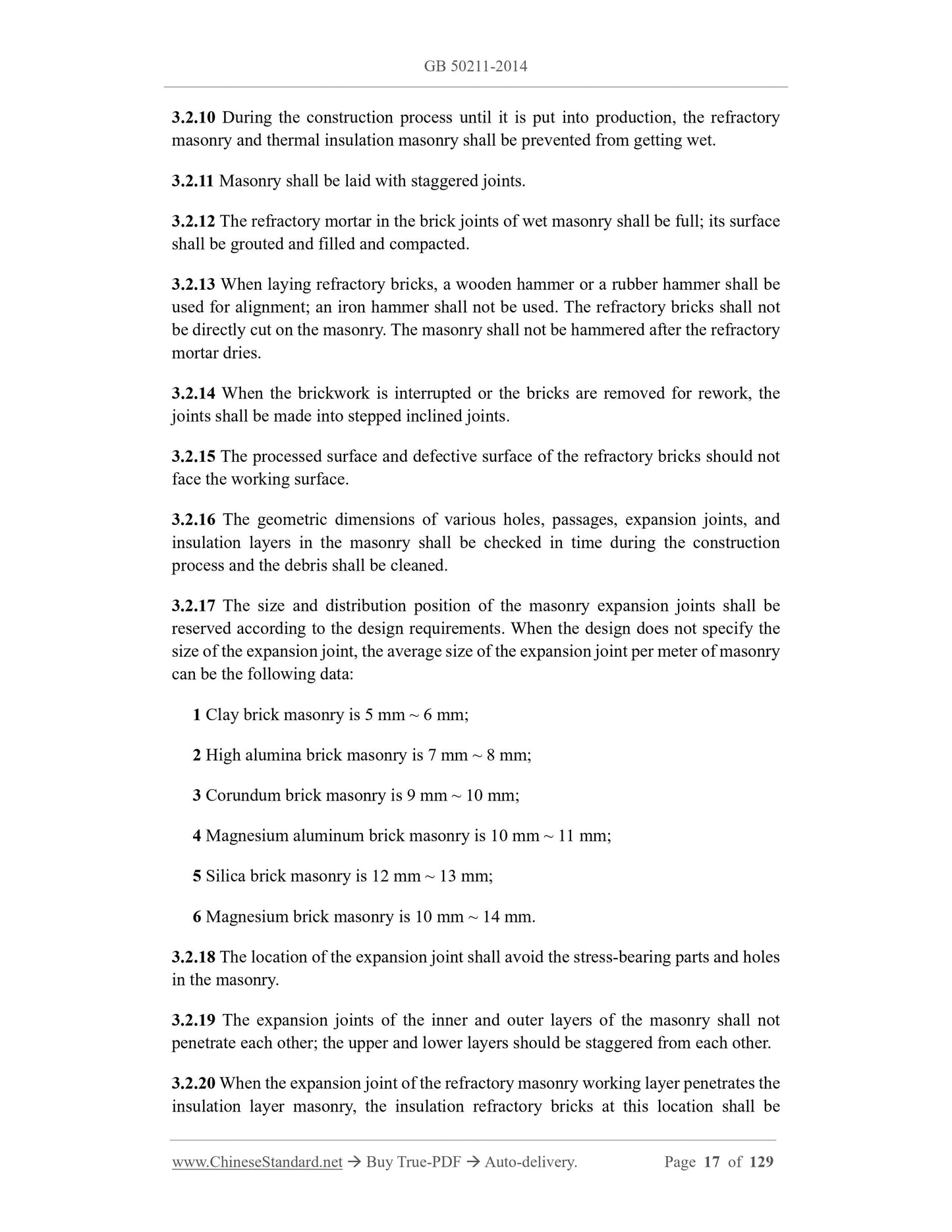
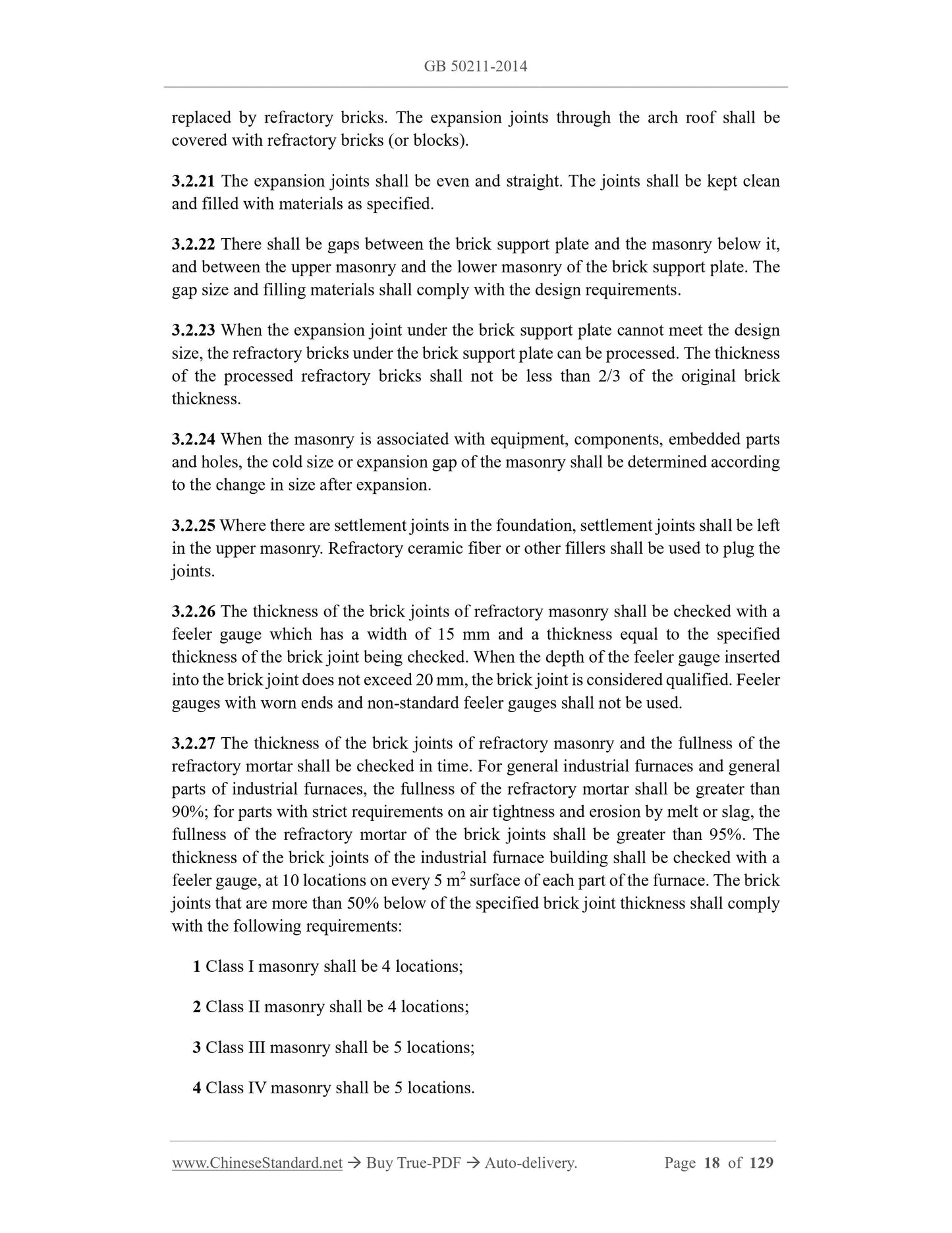
3.2.10 During the construction process until it is put into production, the refractory
masonry and thermal insulation masonry shall be prevented from getting wet.
3.2.11 Masonry shall be laid with staggered joints.
3.2.12 The refractory mortar in the brick joints of wet masonry shall be full; its surface
shall be grouted and filled and compacted.
3.2.13 When laying refractory bricks, a wooden hammer or a rubber hammer shall be
used for alignment; an iron hammer shall not be used. The refractory bricks shall not
be directly cut on the masonry. The masonry shall not be hammered after the refractory
mortar dries.
3.2.14 When the brickwork is interrupted or the bricks are removed for rework, the
joints shall be made into stepped inclined joints.
3.2.15 The processed surface and defective surface of the refractory bricks should not
face the working surface.
3.2.16 The geometric dimensions of various holes, passages, expansion joints, and
insulation layers in the masonry shall be checked in time during the construction
process and the debris shall be cleaned.
3.2.17 The size and distribution position of the masonry expansion joints shall be
reserved according to the design requirements. When the design does not specify the
size of the expansion joint, the average size of the expansion joint per meter of masonry
can be the following data:
1 Clay brick masonry is 5 mm ~ 6 mm;
2 High alumina brick masonry is 7 mm ~ 8 mm;
3 Corundum brick masonry is 9 mm ~ 10 mm;
4 Magnesium aluminum brick masonry is 10 mm ~ 11 mm;
5 Silica brick masonry is 12 mm ~ 13 mm;
6 Magnesium brick masonry is 10 mm ~ 14 mm.
3.2.18 The location of the expansion joint shall avoid the stress-bearing parts and holes
in the masonry.
3.2.19 The expansion joints of the inner and outer layers of the masonry shall not
penetrate each other; the upper and lower layers should be staggered from each other.
3.2.20 When the expansion joint of the refractory masonry working layer penetrates the
insulation layer masonry, the insulation refractory bricks at this location shall be
replaced by refractory bricks. The expansion joints through the arch roof shall be
covered with refractory bricks (or blocks).
3.2.21 The expansion joints shall be even and straight. The joints shall be kept clean
and filled with materials as specified.
3.2.22 There shall be gaps between the brick support plate and the masonry below it,
and between the upper masonry and the lower masonry of the brick support plate. The
gap size and filling materials shall comply with the design requirements.
3.2.23 When the expansion joint under the brick support plate cannot meet the design
size, the refractory bricks under the brick support plate can be processed. The thickness
of the processed refractory bricks shall not be less than 2/3 of the original brick
thickness.
3.2.24 When the masonry is associated with equipment, components, embedded parts
and holes, the cold size or expansion gap of the masonry shall be determined according
to the change in size after expansion.
3.2.25 Where there are settlement joints in the foundation, settlement joints shall be left
in the upper masonry. Refractory ceramic fiber or other fillers shall be used to plug the
joints.
3.2.26 The thickness of the brick joints of refractory masonry shall be checked with a
feeler gauge which has a width of 15 mm and a thickness equal to the specified
thickness of the brick joint being checked. When the depth of the feeler gauge inserted
into the brick joint does not exceed 20 mm, the brick joint is considered qualified. Feeler
gauges with worn ends and non-standard feeler gauges shall not be used.
3.2.27 The thickness of the brick joints of refractory masonry and the fullness of the
refractory mortar shall be checked in time. For general industrial furnaces and general
parts of industrial furnaces, the fullness of the refractory mortar shall be greater than
90%; for parts with strict requirements on air tightness and erosion by melt or slag, the
fullness of the refractory mortar of the brick joints shall be greater than 95%. The
thickness of the brick joints of the industrial furnace building shall be checked with a
feeler gauge, at 10 locations on every 5 m2 surface of each part of the furnace. The brick
joints that are more than 50% below of the specified brick joint thickness shall comply
with the following requirements:
1 Class I masonry shall be 4 locations;
2 Class II masonry shall be 4 locations;
3 Class III masonry shall be 5 locations;
4 Class IV masonry shall be 5 locations.
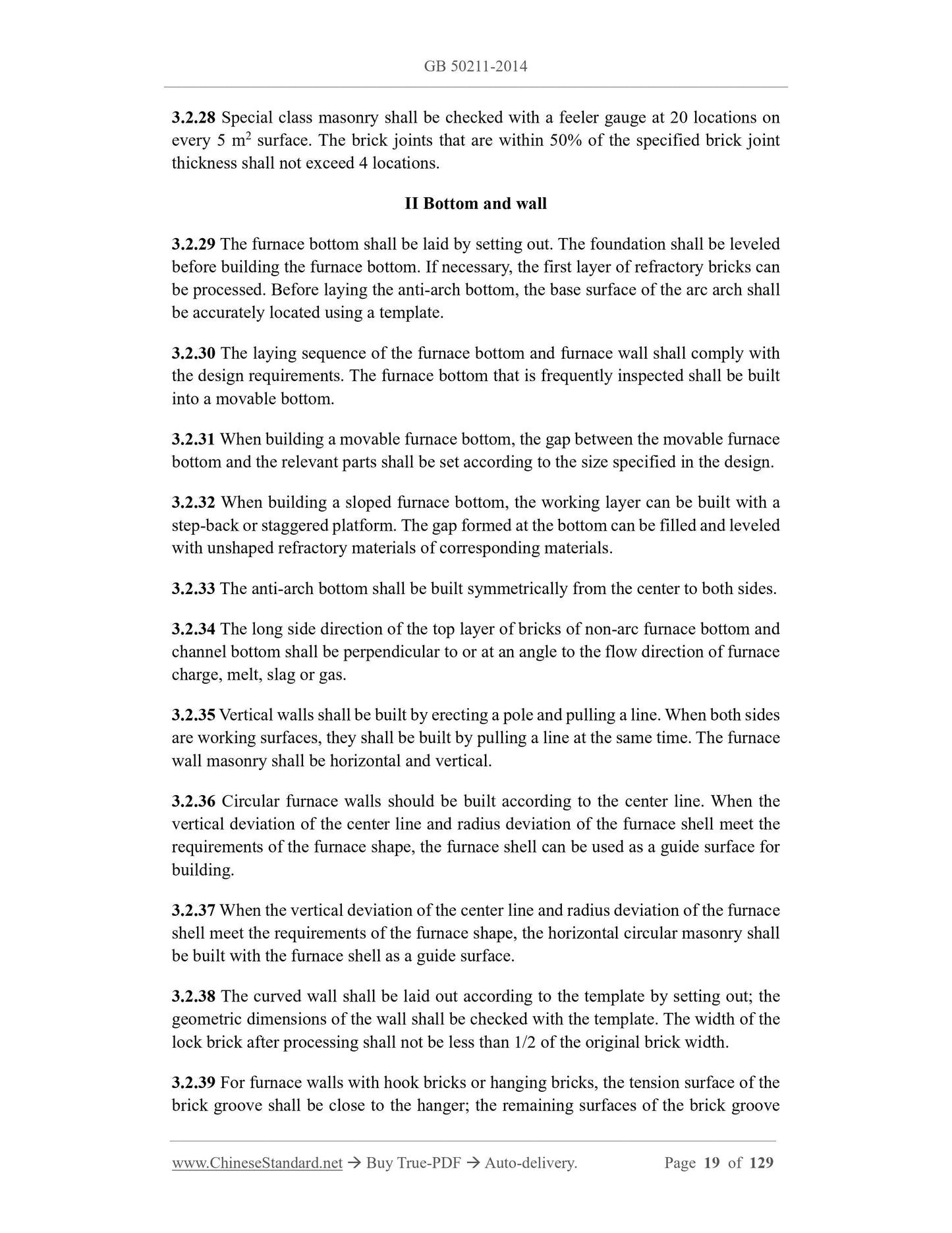
3.2.28 Special class masonry shall be checked with a feeler gauge at 20 locations on
every 5 m2 surface. The brick joints that are within 50% of the specified brick joint
thickness shall not exceed 4 locations.
II Bottom and wall
3.2.29 The furnace bottom shall be laid by setting out. The foundation shall be leveled
before building the furnace bottom. If necessary, the first layer of refractory bricks can
be processed. Before laying the anti-arch bottom, the base surface of the arc arch shall
be accurately located using a template.
3.2.30 The laying sequence of the furnace bottom and furnace wall shall comply with
the design requirements. The furnace bottom that is frequently inspected shall be built
into a movable bottom.
3.2.31 When building a movable furnace bottom, the gap between the movable furnace
bottom and the relevant parts shall be set according to the size specified in the design.
3.2.32 When building a sloped furnace bottom, the working layer can be built with a
step-back or staggered platform. The gap formed at the bottom can be filled and leveled
with unshaped refractory materials of corresponding materials.
3.2.33 The anti-arch bottom shall be built symmetrically from the center to both sides.
3.2.34 The long side direction of the top layer of bricks of non-arc furnace bottom and
channel bottom shall be perpendicular to or at an angle to the flow direction of furnace
charge, melt, slag or gas.
3.2.35 Vertical walls shall be built by erecting a pole and pulling a line. When both sides
are working surfaces, they shall be built by pulling a line at the same time. The furnace
wall masonry shall be horizontal and vertical.
3.2.36 Circular furnace walls should be built according to the center line. When the
vertical deviation of the center line and radius deviation of the furnace shell meet the
requirements of the furnace shape, the furnace shell can be used as a guide surface for
building.
3.2.37 When the vertical deviation of the center line and radius deviation of the furnace
shell meet the requirements of the furnace shape, the horizontal circular masonry shall
be built with the furnace shell as a guide surface.
3.2.38 The curved wall shall be laid out according to the template by setting out; the
geometric dimensions of the wall shall be checked with the template. The width of the
lock brick after processing shall not be less than 1/2 of the original brick width.
3.2.39 For furnace walls with hook bricks or hanging bricks, the tension surface of the
brick groove shall be close to the hanger; the remaining surfaces of the brick groove
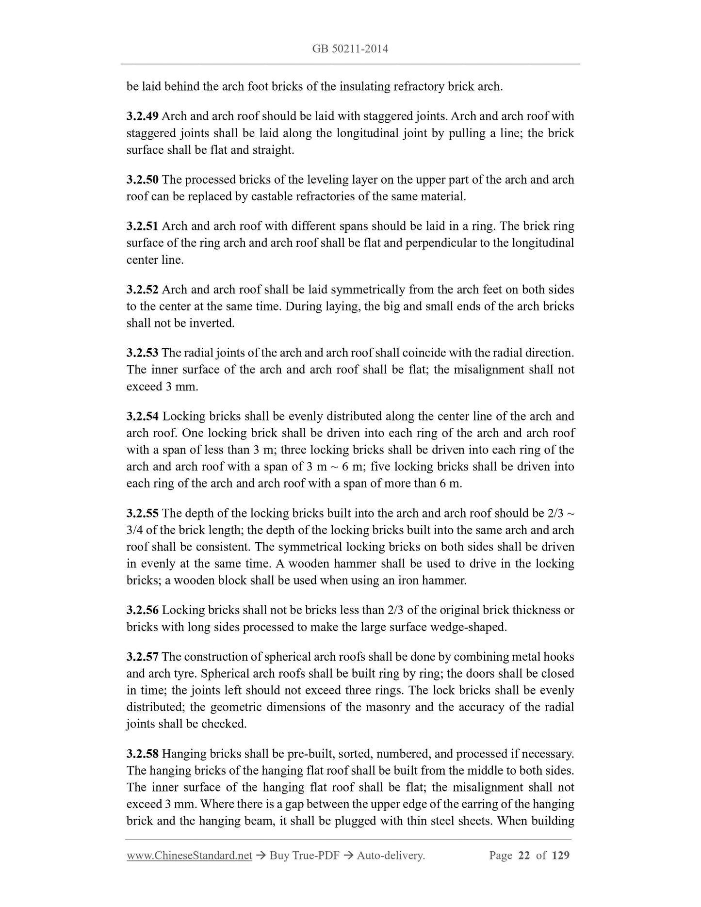
be laid behind the arch foot bricks of the insulating refractory brick arch.
3.2.49 Arch and arch roof should be laid with staggered joints. Arch and arch roof with
staggered joints shall be laid along the longitudinal joint by pulling a line; the brick
surface shall be flat and straight.
3.2.50 The processed bricks of the leveling layer on the upper part of the arch and arch
roof can be replaced by castable refractories of the same material.
3.2.51 Arch and arch roof with different spans should be laid in a ring. The brick ring
surface of the ring arch and arch roof shall be flat and perpendicular to the longitudinal
center line.
3.2.52 Arch and arch roof shall be laid symmetrically from the arch feet on both sides
to the center at the same time. During laying, the big and small ends of the arch bricks
shall not be inverted.
3.2.53 The radial joints of the arch and arch roof shall coincide with the radial direction.
The inner surface of the arch and arch roof shall be flat; the misalignment shall not
exceed 3 mm.
3.2.54 Locking bricks shall be evenly distributed along the center line of the arch and
arch roof. One locking brick shall be driven into each ring of the arch and arch roof
with a span of less than 3 m; three locking bricks shall be driven into each ring of the
arch and arch roof with a span of 3 m ~ 6 m; five locking bricks shall be driven into
each ring of the arch and arch roof with a span of more than 6 m.
3.2.55 The depth of the locking bricks built into the arch and arch roof should be 2/3 ~
3/4 of the brick length; the depth of the locking bricks built into the same arch and arch
roof shall be consistent. The symmetrical locking bricks on both sides shall be driven
in evenly at the same time. A wooden hammer shall be used to drive in the locking
bricks; a wooden block shall be used when using an iron hammer.
3.2.56 Locking bricks shall no...
View full details