Skip to product information
1 of 12

www.ChineseStandard.us -- Field Test Asia Pte. Ltd.

GB 50191-2012 English PDF

GB 50191-2012 English PDF

Regular price $305.00
Regular price Sale price $305.00
Sale Sold out
Shipping calculated at checkout.
GB 50191-2012: Code for seismic design of special structures
Delivery: 9 seconds. Download (& Email) true-PDF + Invoice.
Get Quotation: Click GB 50191-2012 (Self-service in 1-minute)
Historical versions (Master-website): GB 50191-2012
Preview True-PDF (Reload/Scroll-down if blank)

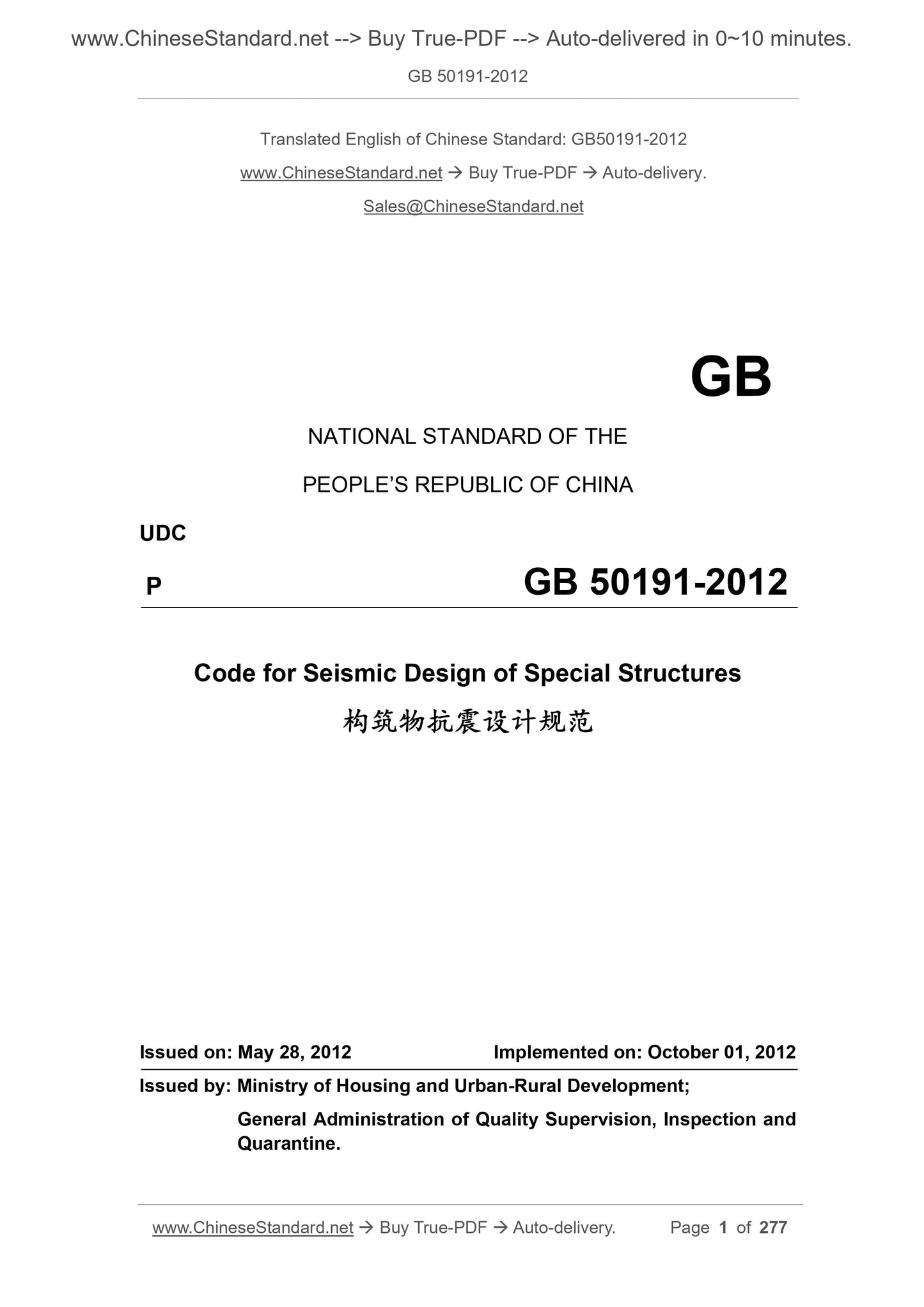
GB 50191-2012
NATIONAL STANDARD OF THE
PEOPLE’S REPUBLIC OF CHINA
UDC
P GB 50191-2012
Code for Seismic Design of Special Structures
ISSUED ON: MAY 28, 2012
IMPLEMENTED ON: OCTOBER 01, 2012
Issued by: Ministry of Housing and Urban-Rural Development;
General Administration of Quality Supervision, Inspection and
Quarantine.
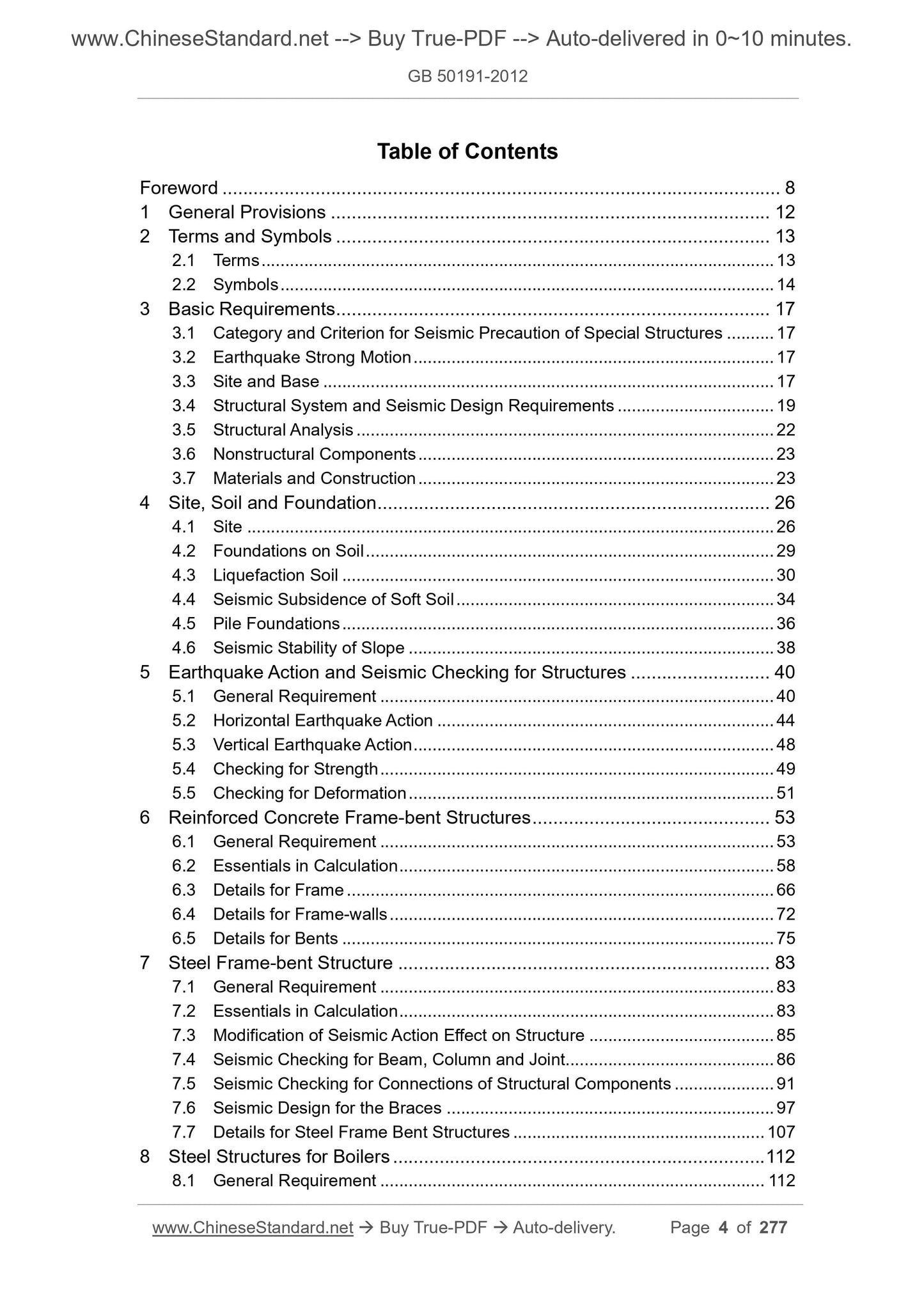
Table of Contents
Foreword ... 8 
1 General Provisions ... 12 
2 Terms and Symbols ... 13 
2.1 Terms ... 13 
2.2 Symbols ... 14 
3 Basic Requirements ... 17 
3.1 Category and Criterion for Seismic Precaution of Special Structures ... 17 
3.2 Earthquake Strong Motion ... 17 
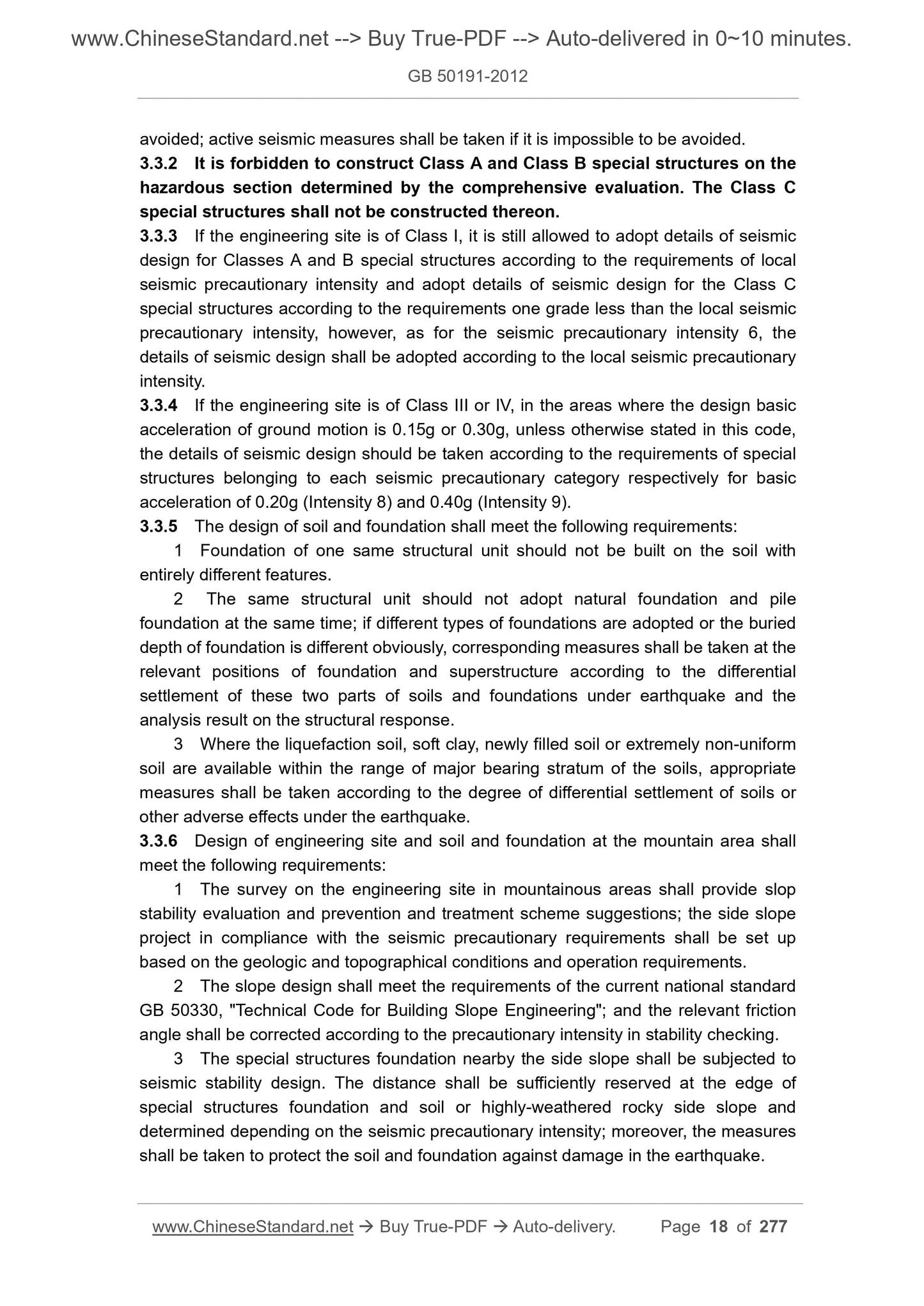
3.3 Site and Base ... 17 
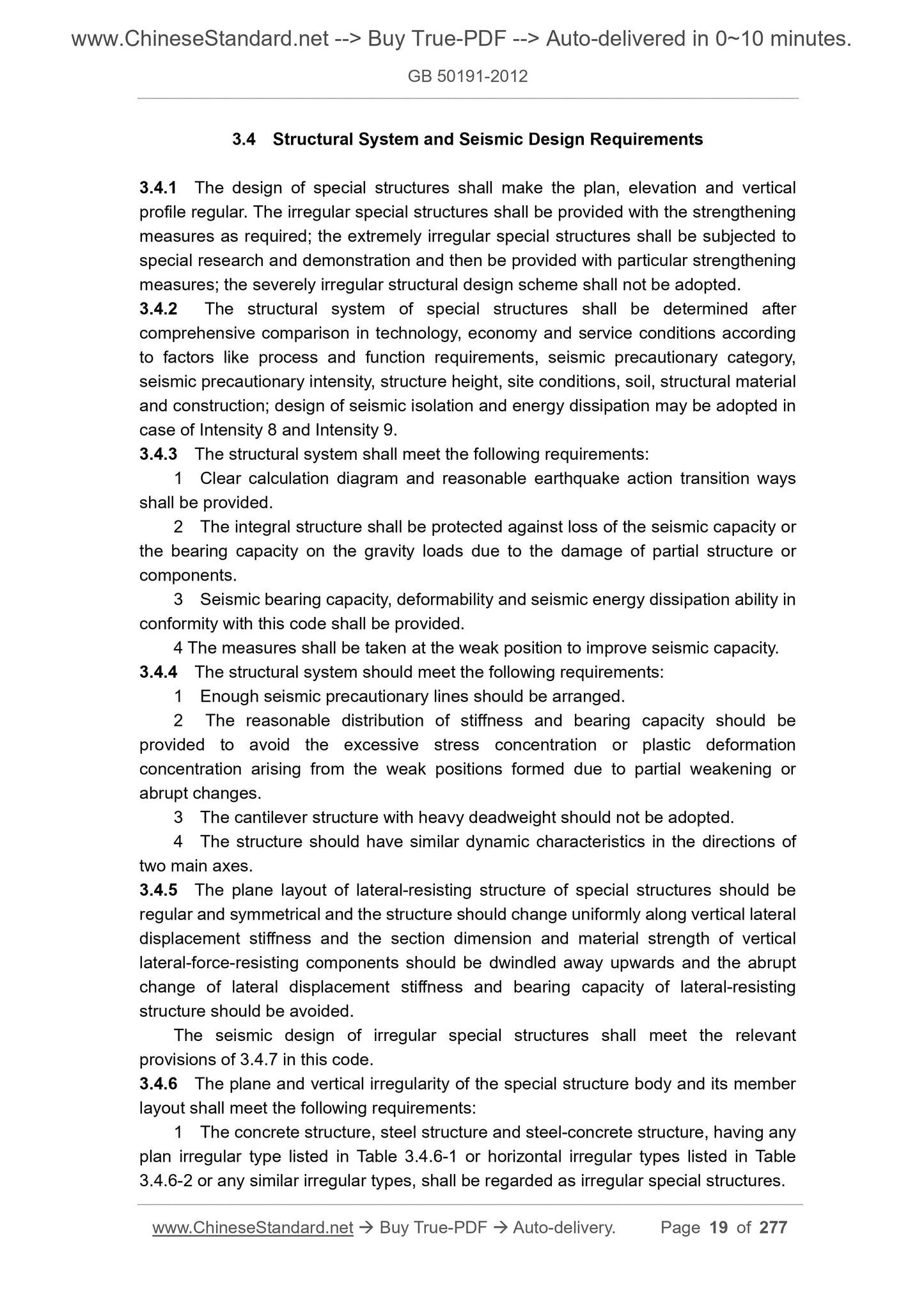
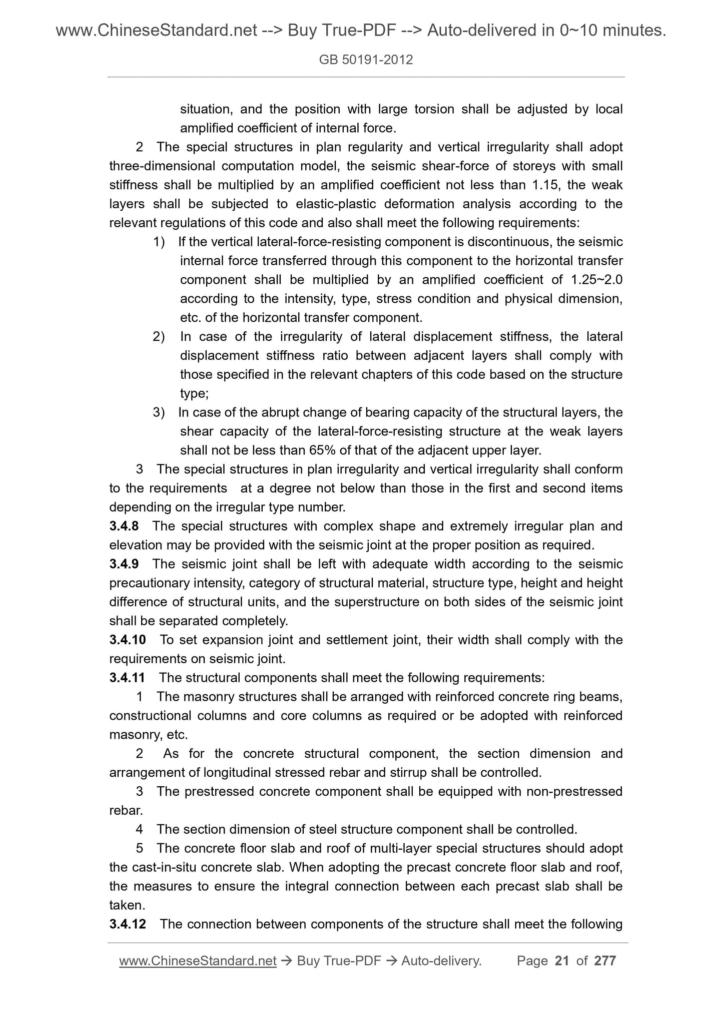
3.4 Structural System and Seismic Design Requirements ... 19 
3.5 Structural Analysis ... 22 
3.6 Nonstructural Components ... 23 
3.7 Materials and Construction ... 23 
4 Site, Soil and Foundation ... 26 
4.1 Site ... 26 
4.2 Foundations on Soil ... 29 
4.3 Liquefaction Soil ... 30 
4.4 Seismic Subsidence of Soft Soil ... 34 
4.5 Pile Foundations ... 36 
4.6 Seismic Stability of Slope ... 38 
5 Earthquake Action and Seismic Checking for Structures ... 40 
5.1 General Requirement ... 40 
5.2 Horizontal Earthquake Action ... 44 
5.3 Vertical Earthquake Action ... 48 
5.4 Checking for Strength ... 49 
5.5 Checking for Deformation ... 51 
6 Reinforced Concrete Frame-bent Structures ... 53 
6.1 General Requirement ... 53 
6.2 Essentials in Calculation ... 58 
6.3 Details for Frame ... 66 
6.4 Details for Frame-walls ... 72 
6.5 Details for Bents ... 75 
7 Steel Frame-bent Structure ... 83 
7.1 General Requirement ... 83 
7.2 Essentials in Calculation ... 83 
7.3 Modification of Seismic Action Effect on Structure ... 85 
7.4 Seismic Checking for Beam, Column and Joint... 86 
7.5 Seismic Checking for Connections of Structural Components ... 91 
7.6 Seismic Design for the Braces ... 97 
7.7 Details for Steel Frame Bent Structures ... 107 
8 Steel Structures for Boilers ... 112 
8.1 General Requirement ... 112 
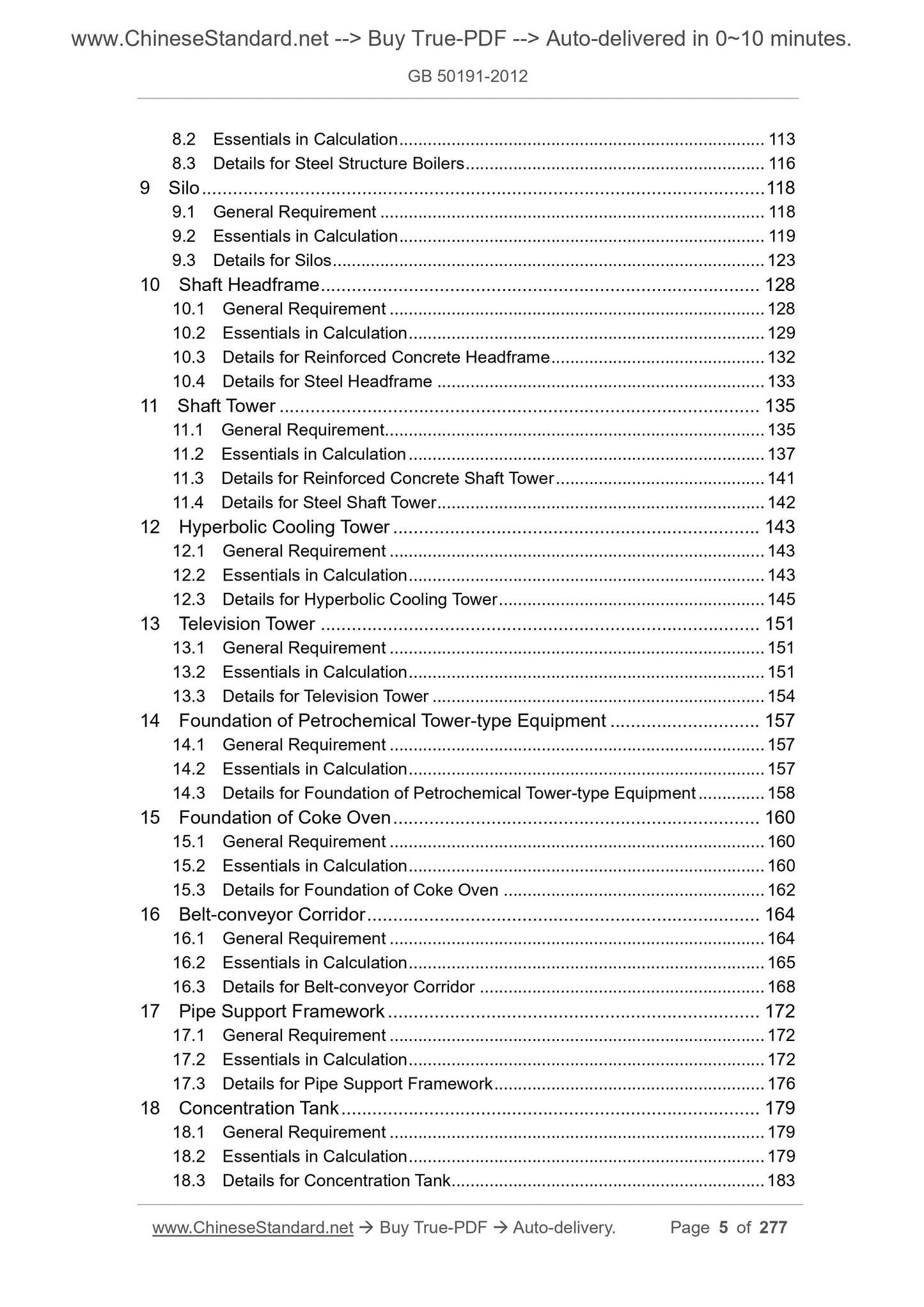
8.2 Essentials in Calculation ... 113 
8.3 Details for Steel Structure Boilers ... 116 
9 Silo ... 118 
9.1 General Requirement ... 118 
9.2 Essentials in Calculation ... 119 
9.3 Details for Silos ... 123 
10 Shaft Headframe ... 128 
10.1 General Requirement ... 128 
10.2 Essentials in Calculation ... 129 
10.3 Details for Reinforced Concrete Headframe ... 132 
10.4 Details for Steel Headframe ... 133 
11 Shaft Tower ... 135 
11.1 General Requirement ... 135 
11.2 Essentials in Calculation ... 137 
11.3 Details for Reinforced Concrete Shaft Tower ... 141 
11.4 Details for Steel Shaft Tower ... 142 
12 Hyperbolic Cooling Tower ... 143 
12.1 General Requirement ... 143 
12.2 Essentials in Calculation ... 143 
12.3 Details for Hyperbolic Cooling Tower ... 145 
13 Television Tower ... 151 
13.1 General Requirement ... 151 
13.2 Essentials in Calculation ... 151 
13.3 Details for Television Tower ... 154 
14 Foundation of Petrochemical Tower-type Equipment ... 157 
14.1 General Requirement ... 157 
14.2 Essentials in Calculation ... 157 
14.3 Details for Foundation of Petrochemical Tower-type Equipment ... 158 
15 Foundation of Coke Oven ... 160 
15.1 General Requirement ... 160 
15.2 Essentials in Calculation ... 160 
15.3 Details for Foundation of Coke Oven ... 162 
16 Belt-conveyor Corridor ... 164 
16.1 General Requirement ... 164 
16.2 Essentials in Calculation ... 165 
16.3 Details for Belt-conveyor Corridor ... 168 
17 Pipe Support Framework ... 172 
17.1 General Requirement ... 172 
17.2 Essentials in Calculation ... 172 
17.3 Details for Pipe Support Framework ... 176 
18 Concentration Tank ... 179 
18.1 General Requirement ... 179 
18.2 Essentials in Calculation ... 179 
18.3 Details for Concentration Tank ... 183 
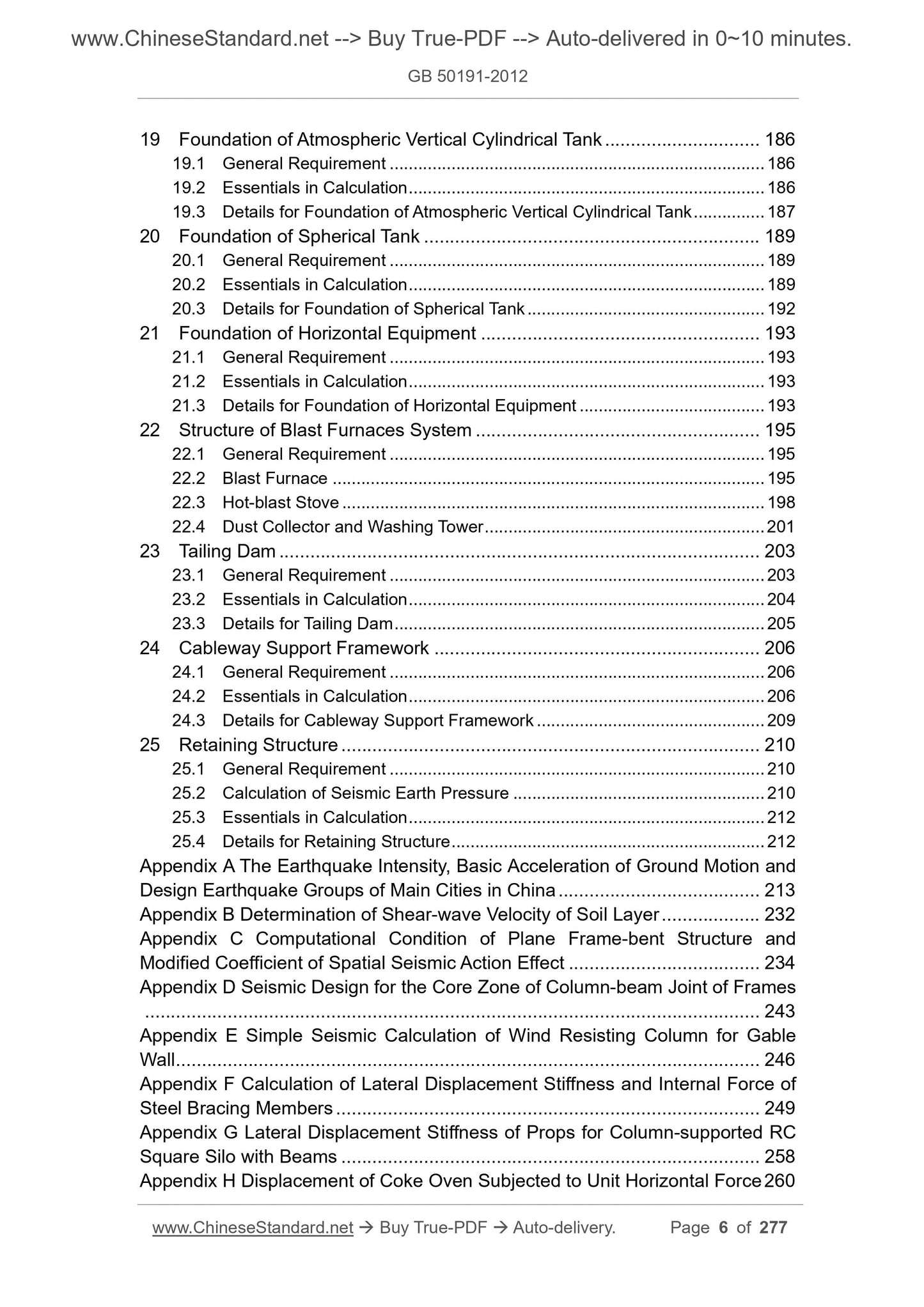
19 Foundation of Atmospheric Vertical Cylindrical Tank ... 186 
19.1 General Requirement ... 186 
19.2 Essentials in Calculation ... 186 
19.3 Details for Foundation of Atmospheric Vertical Cylindrical Tank ... 187 
20 Foundation of Spherical Tank ... 189 
20.1 General Requirement ... 189 
20.2 Essentials in Calculation ... 189 
20.3 Details for Foundation of Spherical Tank ... 192 
21 Foundation of Horizontal Equipment ... 193 
21.1 General Requirement ... 193 
21.2 Essentials in Calculation ... 193 
21.3 Details for Foundation of Horizontal Equipment ... 193 
22 Structure of Blast Furnaces System ... 195 
22.1 General Requirement ... 195 
22.2 Blast Furnace ... 195 
22.3 Hot-blast Stove ... 198 
22.4 Dust Collector and Washing Tower ... 201 
23 Tailing Dam ... 203 
23.1 General Requirement ... 203 
23.2 Essentials in Calculation ... 204 
23.3 Details for Tailing Dam ... 205 
24 Cableway Support Framework ... 206 
24.1 General Requirement ... 206 
24.2 Essentials in Calculation ... 206 
24.3 Details for Cableway Support Framework ... 209 
25 Retaining Structure ... 210 
25.1 General Requirement ... 210 
25.2 Calculation of Seismic Earth Pressure ... 210 
25.3 Essentials in Calculation ... 212 
25.4 Details for Retaining Structure ... 212 
Appendix A The Earthquake Intensity, Basic Acceleration of Ground Motion and
Design Earthquake Groups of Main Cities in China ... 213 
Appendix B Determination of Shear-wave Velocity of Soil Layer ... 232 
Appendix C Computational Condition of Plane Frame-bent Structure and
Modified Coefficient of Spatial Seismic Action Effect ... 234 
Appendix D Seismic Design for the Core Zone of Column-beam Joint of Frames
... 243 
Appendix E Simple Seismic Calculation of Wind Resisting Column for Gable
Wall ... 246 
Appendix F Calculation of Lateral Displacement Stiffness and Internal Force of
Steel Bracing Members ... 249 
Appendix G Lateral Displacement Stiffness of Props for Column-supported RC
Square Silo with Beams ... 258 
Appendix H Displacement of Coke Oven Subjected to Unit Horizontal Force 260 
Appendix J Calculation of Horizontal Seismic Action on Corridor ... 264 
Appendix K Simplified Calculation for the Earthquake-induced Liquefaction
Discrimination of Tailing Dam ... 267 
Appendix L Basic Requirements for Seismic Time-history Analysis of Tailing
Dam ... 269 
Appendix M Seismic Stability Analysis of Tailing Dam ... 270 
Appendix N Seismic Earth Pressure with Relative Displacement between Wall
and Soil ... 272 
Explanation of Wording in This Code ... 276 
List of Quoted Standards ... 277 
1 General Provisions
1.0.1 This code is formulated with a view to implementing the national laws and
regulations on the seismic protection and disaster mitigation and the prevention-first
policy so that the special structures can relieve seismic damage after seismic
fortification to avoid casualties or complete loss of use function and minimize economic
loss.
1.0.2 This code is applicable to seismic design of special structures at the area with
Intensity 6 ~ Intensity 9 seismic precautionary intensity.
1.0.3 The seismic precautionary objective for the special structures, subjected to the
seismic design according to this code, within 50-year design service life: the main
structure shall not be damaged or not required to be repaired and may continue in
service in case of being suffered from the frequent earthquakes below seismic
precautionary intensity of this area; the damaged structure may continue in service
after general repair in case of being suffered from precautionary earthquake equivalent
to seismic precautionary intensity of this area; the integral collapse shall be avoided in
case of being suffered from the rare earthquake higher than seismic precautionary
intensity of this area.
1.0.4 The special structures with Intensity 6 or above seismic precautionary
intensity must be subjected to seismic design.
1.0.5 The seismic precautionary intensity and the design parameters of ground
motion must be determined according to the documents (graphic documents)
approved and issued by the national authority and adopted according to the
approval documents.
1.0.6 The seismic precautionary intensity shall adopt the basic seismic intensity in the
current national standard "Seismic Ground Motion Parameter Zonation Map of China"
GB 18306 or the intensity corresponding to the design basic acceleration value of
ground motion in this code. The engineering site subjected to the seismic safety
evaluation should be subjected to seismic fortification according to approved seismic
precautionary intensity or the design parameters of ground motion.
1.0.7 The seismic design of special structures shall meet not only the requirements
stipulated in this code, but also the provisions of the related current national standards.
2 Terms and Symbols
2.1 Terms
2.1.1 Basic seismic intensity
The seismic intensity that may be met at general site conditions with a probability over
10% within a term of 50 years, which is equivalent to the seismic intensity once in 475
years.
2.1.2 Seismic precautionary intensity
The seismic intensity approved by national authority as the seismic precautionary basis
of an area, generally using basic seismic intensity.
2.1.3 Seismic precautionary criterion
The standard for judging the seismic precautionary requirements, which is dependent
on the seismic precautionary intensity or the design parameters of ground motion and
the seismic precautionary category of special structures.
2.1.4 Earthquake action
The dynamic action of structure caused by ground motion, including horizontal
earthquake action and vertical earthquake action.
2.1.5 Design parameters of ground motion
The seismic acceleration-time curve (speed and displacement), the response spectrum
of acceleration, and the peak acceleration used in seismic design.
2.1.6 Design basic acceleration of ground motion
The design value of seismic acceleration exceeding the probability of 10% during the
50-year design reference period.
2.1.7 Characteristic period of ground motion
The period value corresponding to the starting point of the descending branch reflecting
such factors as the earthquake magnitude, epicentral distance and site class in the
seismic influence coefficient curve used for the seismic design.
2.1.8 Seismic influence coefficient
The assembly average of the ratio between the maximum acceleration reaction and
gravity acceleration of single-particle elastic system under the earthquake action.
2.1.9 Site
The place where the engineering groups with similar response spectrum features are
located.
2.1.10 Seismic concept design of special structures
The design process of making the process arrangement and structural selection for the
special structures and of determining detailed constructions, based on the design
fundamental design principles and design concept obtained from the past experiences
in earthquake disasters and projects.
2.1.11 Seismic action effect
Internal force (shear-force, bending moment, axial force and torsion moment, etc.) or
deformation (linear displacement and angular displacement, etc.) of the structure under
the earthquake action.
2.1.12 Modified coefficient of seismic action effect
The coefficient for modification of seismic action effect in the structure or components
design influenced by the simplification of structural calculation model and redistribution
of elastic-plastic internal force or other factors.
2.1.13 Modified coefficient of seismic bearing capacity
The coefficient for modifying the design section bearing capacities, which are specified
in different codes for the design of material structures, into the design seismic bearing
capacity in the seismic checking of structural components sections, as there are
differences in the static force, seismic design reliability and seismic performance
between different components.
2.1.14 Seismic measures
The seismic design excluding the earthquake action calculation and resistance
calculation, including basic requirements of seismic design, details of seismic design
and seismic measures of soil and foundation.
2.1.15 Details of seismic design
All the detailed requirements that must be taken for the structural and nonstructural
parts according to seismic concept design principles, requiring no calculation generally.
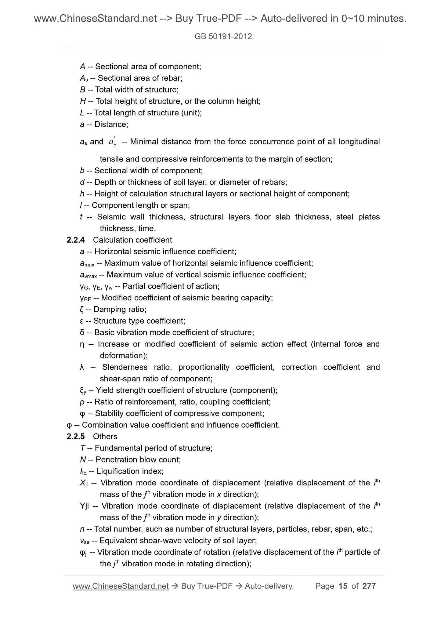
2.2 Symbols
2.2.1 Action and action effect
FEk and FEvk -- Characteristic value for total horizontal and vertical earthquake action
of the structure;
GE and Geq -- Representative value of structure (component) gravity load and total
equivalent gravity load in earthquake;
wk -- Characteristic value of wind load;
SE -- Seismic action effect (bending moment, axial force, shear-force, stress and
deformation);
S -- Fundamental combination of seismic action effect and other load effects;
Sk -- Effect of action or characteristic value of load;
M -- Bending moment;
N -- Axial force;
V -- Shear-force;
p -- Pressure on bottom of foundation;
u -- Lateral displacement;
θ -- Displacement angle of structural layers.
2.2.2 Material properties and resistance
K -- Stiffness of structure (component);
R -- Bearing capacity of structural component;
f, fk, fE -- Design value, characteristic value and seismic design value of various
material strength (including the bearing capacity of soil) respectively;
E -- Elasticity modulus of the material;
[θ] -- Displacement angle limit of structural layers.
2.2.3 Geometric parameters
A -- Sectional area of component;
As -- Sectional area of rebar;
B -- Total width of structure;
H -- Total height of structure, or the column height;
L -- Total length of structure (unit);
a -- Distance;
as and 'sa -- Minimal distance from the force concurrence point of all longitudinal
tensile and compressive reinforcements to the margin of section;
b -- Sectional width of component;
d -- Depth or thickness of soil layer, or diameter of rebars;
h -- Height of calculation s...
View full details