Skip to product information
1 of 12

www.ChineseStandard.us -- Field Test Asia Pte. Ltd.

GB 50177-2005 English PDF

GB 50177-2005 English PDF

Regular price $125.00
Regular price Sale price $125.00
Sale Sold out
Shipping calculated at checkout.
GB 50177-2005: Design code for hydrogen station
Delivery: 9 seconds. Download (& Email) true-PDF + Invoice.
Get Quotation: Click GB 50177-2005 (Self-service in 1-minute)
Historical versions (Master-website): GB 50177-2005
Preview True-PDF (Reload/Scroll-down if blank)

GB 50177-2005
UDC GB
NATIONAL STANDARD OF THE
PEOPLE’S REPUBLIC OF CHINA
P GB 50177-2005
Design Code for Hydrogen Station
ISSUED ON: APRIL 15, 2005
IMPLEMENTED ON: OCTOBER 01, 2005
Issued by: Ministry of Construction of the People's Republic of China;
General Administration of Quality Supervision, Inspection and
Quarantine of the People's Republic of China.
Table of Contents
Foreword ... 4
1 General Provisions ... 6
2 Terms ... 6
3 General Layout ... 8
4 Process System ... 10
5 Equipment Selection ... 13
6 Process Layout ... 15
7 Building Structure ... 17
8 Electrical and Instrument Control ... 19
9 Lightning Protection and Earthing ... 21
10 Water Supply and Drainage and Fire Fighting ... 22
11 Heating and Ventilation ... 23
12 Hydrogen Gas Pipeline ... 23
Appendix A Division of Rating for Explosion Hazard Zone in Hydrogen Station ... 27
Appendix B Minimum Clear Distance between Overhead Hydrogen Gas Pipeline
and Other Overhead Pipeline in Plant Area, Hydrogen Station and Shop ... 29
Appendix C Minimum Clear Distance between Overhead Hydrogen Gas Pipeline in
Plant Area and Buildings and Structures ... 30
Appendix D Minimum Clear Distance between Hydrogen Gas Pipeline Buried
Directly in Plant Area and Other Buried Pipelines ... 31
Appendix E Minimum Clear Distance between Hydrogen Gas Pipeline Buried
Directly in Plant Area and Buildings and Structures ... 32
Explanation of Wording in This Code ... 33
1 General Provisions
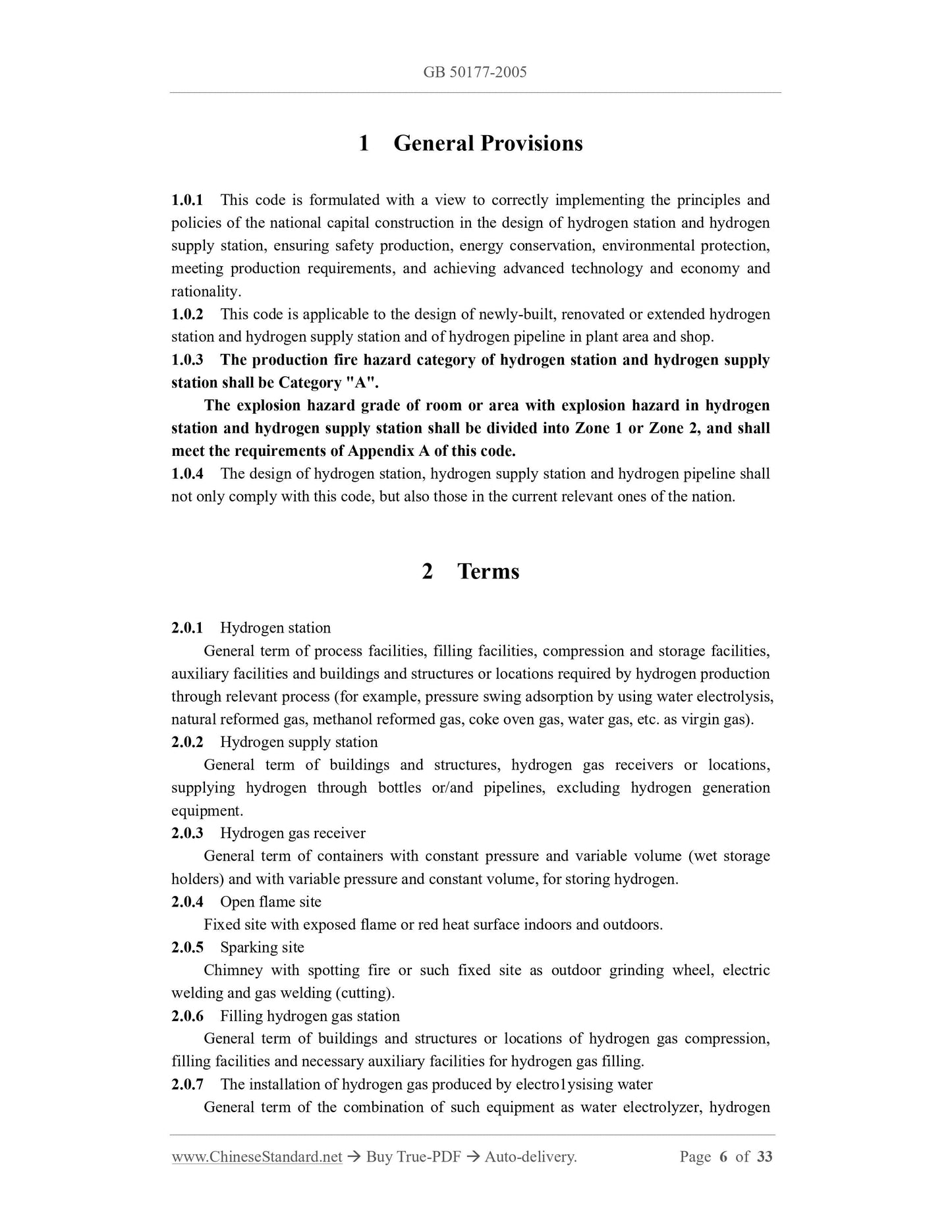
1.0.1 This code is formulated with a view to correctly implementing the principles and
policies of the national capital construction in the design of hydrogen station and hydrogen
supply station, ensuring safety production, energy conservation, environmental protection,
meeting production requirements, and achieving advanced technology and economy and
rationality.
1.0.2 This code is applicable to the design of newly-built, renovated or extended hydrogen
station and hydrogen supply station and of hydrogen pipeline in plant area and shop.
1.0.3 The production fire hazard category of hydrogen station and hydrogen supply
station shall be Category "A".
The explosion hazard grade of room or area with explosion hazard in hydrogen
station and hydrogen supply station shall be divided into Zone 1 or Zone 2, and shall
meet the requirements of Appendix A of this code.
1.0.4 The design of hydrogen station, hydrogen supply station and hydrogen pipeline shall
not only comply with this code, but also those in the current relevant ones of the nation.
2 Terms
2.0.1 Hydrogen station
General term of process facilities, filling facilities, compression and storage facilities,
auxiliary facilities and buildings and structures or locations required by hydrogen production
through relevant process (for example, pressure swing adsorption by using water electrolysis,
natural reformed gas, methanol reformed gas, coke oven gas, water gas, etc. as virgin gas).
2.0.2 Hydrogen supply station
General term of buildings and structures, hydrogen gas receivers or locations,
supplying hydrogen through bottles or/and pipelines, excluding hydrogen generation
equipment.
2.0.3 Hydrogen gas receiver
General term of containers with constant pressure and variable volume (wet storage
holders) and with variable pressure and constant volume, for storing hydrogen.
2.0.4 Open flame site
Fixed site with exposed flame or red heat surface indoors and outdoors.
2.0.5 Sparking site
Chimney with spotting fire or such fixed site as outdoor grinding wheel, electric
welding and gas welding (cutting).
2.0.6 Filling hydrogen gas station
General term of buildings and structures or locations of hydrogen gas compression,
filling facilities and necessary auxiliary facilities for hydrogen gas filling.
2.0.7 The installation of hydrogen gas produced by electro1ysising water
General term of the combination of such equipment as water electrolyzer, hydrogen
(oxygen) gas-liquid separator, hydrogen (oxygen) cooler and hydrogen (oxygen) washer
which take water as the raw material.
2.0.8 The system of hydrogen gas produced by electrolysising water
General term of process system composed of the installation of hydrogen gas produced
by electro1ysising water and such operating units as hydrogen gas pressurizing, storage,
purification and filling, by producing hydrogen gas through water electrolysis process.
2.0.9 The installation of hydrogen purification by pressure swing adsorption
General term of the combination of process equipment which takes various gases
containing hydrogen as raw material, passes through multiple adsorption towers, adopts
pressure swing adsorption method and extracts hydrogen from virgin gas.
2.0.10 Hydrogen purification system by pressure swing adsorption
General term of process system composed of pressure swing adsorption device and
such operating units as hydrogen pressurizing, storage, purification and filling, by purifying
and producing hydrogen from various gases containing hydrogen through pressure swing
adsorption method.
2.0.11 The installation of hydrogen gas produced by the methanol transforming
General term of the combination of production equipment for cracking and
transforming methanol and producing hydrogen gas at a certain temperature, by taking
methanol and water as the raw material and adopting the catalytic transformation process.
2.0.12 The low pressure compressor for the hydrogen gas
Hydrogen gas compressor with output pressure less than 1.6MPa.
2.0.13 The middle pressure compressor for the hydrogen gas
Hydrogen gas compressor with output pressure larger than or equal to 1.6MPa and less
than 10.0MPa.
2.0.14 The high pressure compressor for the hydrogen gas
Hydrogen gas compressor with output pressure larger than or equal to 10.0MPa.
2.0.15 The bundle of hydrogen gas cylinders
Gas cylinder unit which is fixed by dedicated frame and the joints of multiple gas
cylinders are connected in parallel and combined through gas collecting tubes.
2.0.16 The hydrogen gas manifolds room
Room equipped with such facilities as manifolds for supplying hydrogen gas with
hydrogen gas cylinder.
2.0.17 The hydrogen gas filling room
Room equipped with such facilities hydrogen gas filling station or the bundle of
hydrogen gas cylinders for filling hydrogen gas cylinders.
2.0.18 Solid cylinder
Cylinder stored with filling pressure gas, gas cylinder with a water volume of 40L and a
design pressure of 12.0~20.0MPa in general.
2.0.19 Empty cylinder
Gas cylinder without internal pressure or remained with residual pressure.
2.0.20 Wet hydrogen
Hydrogen gas with water content reaching saturated or supersaturated state at the
located temperature and pressure.
2.0.21 The hydrogen gas compressor for turning system over
2 The adjacent wall shall be the fire wall without door, window or hole;
3 It shall not be connected with the shop with such fire working as heat treatment,
forging and pressing, and welding;
4 It should be arranged at the end of the plant building, and the fire resistance grade
of the connected building shall not be less than Grade II.
3.0.6 When the solid hydrogen gas cylinders in the hydrogen supply station do not exceed
60 or the floor area does not exceed 500m2, it may be adjacent to the hydrogen shop with
fire resistance grade not less than Grade II or other Category D or E shop with non-fire
working; the adjacent wall shall be the explosion-proof protecting wall without door,
window or hole, and should be arranged near the outer wall or end of the plant building.
3.0.7 Hydrogen bottling room, solid cylinder room and empty cylinder room in the
hydrogen station should be arranged at the edge of the plant building.
4 Process System
4.0.1 The type of hydrogen production system in the hydrogen station shall be determined
in accordance with the following factors:
1 Scale of hydrogen station;
2 Local hydrogen source condition and the supply condition of raw material and
power for hydrogen production;
3 The requirements of the user for hydrogen gas purity and its impurity content as
well as pressure;
4 Characteristic of hydrogen gas use for the user, such as load change condition and
continuity requirements;
5 Technical and economic index and characteristic of hydrogen production system.
4.0.2 The system of hydrogen gas produced by electrolysising water shall be equipped
with the following devices:
1 Pressure regulating device shall be arranged so as to maintain a certain pressure
difference value between water electrolyzer outlet hydrogen gas and oxygen gas, and the
pressure difference value should be less than 0.5kPa;
2 Vent pipe, stop valve and sampling analysis valve shall be arranged between
hydrogen gas outlet pipe and hydrogen gas main and between oxygen gas outlet pipe and
oxygen gas main for each set of the installation of hydrogen gas produced by electrolysising
water;
3 Raw material water preparation device shall be arranged, including raw material
water tank, raw material water pump, etc. The outlet pressure of the raw material water
pump shall be appropriate to the working pressure of the hydrogen production system.
4 Alkaline solution preparation and recovery device shall be arranged. Alkaline
solution filter shall be arranged at the water electrolyzer inlet
4.0.3 The oxygen gas produced through the system of hydrogen gas produced by
electrolysising water may be recycled or directly exhausted to atmosphere as required, and
shall meet the following requirements:
1 When the electrolyzed oxygen gas is recycled, hydrogen autoanalyzer in
oxygen and manual analysis device must be arranged, and hydrogen excess
concentration alarm device in oxygen shall be arranged;
2 When the electrolyzed oxygen gas is recycled or directly exhausted to atmosphere,
measures shall be taken to keep the balance of oxygen gas and hydrogen gas pressure.
4.0.4 The arrangement of the hydrogen purification system by pressure swing adsorption
shall be determined according to the following factors:
1 Pressure, composition and impurity content of intended virgin gas;
2 Pressure, purity and impurity content of product hydrogen gas;
3 Continuity and load change condition of hydrogen gas use;
4 Technical and economic index.
4.0.5 The hydrogen purification system by pressure swing adsorption shall be arranged
with the following devices:
1 Pretreatment facilities of virgin gas (determined according to the impurity content
in virgin gas);
2 Absorber set and program control valve;
3 Refining of hydrogen gas (determined according to the requirements of the user for
hydrogen gas purity, impurity content, etc.);
4 Buffer facilities of hydrogen gas and desorption gas;
5 Desorption gas recycling facilities;
6 Pressurizing facilities of virgin gas, product hydrogen gas and desorption gas shall
be arranged as required.
4.0.6 The system of hydrogen gas produced by the methanol transforming shall be
arranged with the following devices:
1 Storage and conveying device for raw material methanol and desalted water;
2 Methanol transformation reactor and its auxiliary devices, such as heating furnace
or heater, heat recovery equipment;
3 The installation of hydrogen purification by pressure swing adsorption.
4.0.7 Hydrogen gas buffer tank shall be arranged in front of the hydrogen gas compressor.
Multiple hydrogen gas compressors may be connected in parallel to suck gas from the
identical hydrogen gas pipeline, but measures shall be taken to ensure the hydrogen gas at
the gas suction side is positive pressure.
Hydrogen gas receiver shall be arranged at the back of the compressor for conveying
hydrogen gas, and bypass pipe shall be arranged between inlet pipe and exhaust pipe of the
hydrogen gas compressor.
4.0.8 The arrangement of safety protection device of hydrogen gas compressor shall
meet the following requirements:
1 The safety valve shall be arranged between the compressor outlet and the first
stop valve;
2 The inlet and outlet of the compressor shall be arranged with high and low
pressure alarm as well as ultralimit shutdown device;
3 The lubricating oil system shall be arranged with the alarm device for too low
oil pressure or too high oil temperature;
4 The cooling water system of the compressor shall be arranged with
5 Equipment Selection
5.0.1 The design capacity of the hydrogen station should be determined in accordance with
the following factors according to hydrogen gas purpose and use characteristics:
1 Mean hourly consumption per day and night or mean hourly consumption per shift
of various hydrogen equipment;
2 The sum of the maximum hourly consumption of continuous hydrogen equipment
and the mean hourly consumption per day and night or the mean hourly consumption per
shift of residual hydrogen equipment;
3 The hydrogen station with hydrogen gas for export sales shall be determined
according to external hydrogen gas supply volume or market demand condition and
commercial economic scale.
5.0.2 The model, capacity and quantity of the installation of hydrogen gas produced by
electro1ysising water shall be determined according to the following factors through
technical and economical comparison:
1 The installation of hydrogen gas produced by electrolysising water with small
power consumption, low electrolysis chamber voltage, reasonable price and reliable
performance shall be reasonably selected according to hydrogen gas consumption, use
characteristics, etc.;
2 When the newly-built hydrogen station is arranged with 2 or more installations of
hydrogen gas produced by electro1ysising water, their model should be the same;
3 Standby installation of hydrogen gas produced by electro1ysising water should be
arranged; when such measures as gas storage are taken to ensure gas supply without
interruption or synchronous overhaul with gas equipment, the standby installation may not
be arranged.
5.0.3 Such auxiliary equipment for raw material water preparation and alkaline solution
View full details