1
/
of
12
www.ChineseStandard.us -- Field Test Asia Pte. Ltd.
GB 50168-2018 English PDF
Regular price
$920.00
Regular price
Sale price
$920.00
Unit price
/
per
Shipping calculated at checkout.
Couldn't load pickup availability
GB 50168-2018: Standard for construction and acceptance of cable line electric equipment installation engineering
Delivery: 9 seconds. Download (& Email) true-PDF + Invoice.
Get Quotation: Click GB 50168-2018 (Self-service in 1-minute)
Historical versions (Master-website): GB 50168-2018
Preview True-PDF (Reload/Scroll-down if blank)
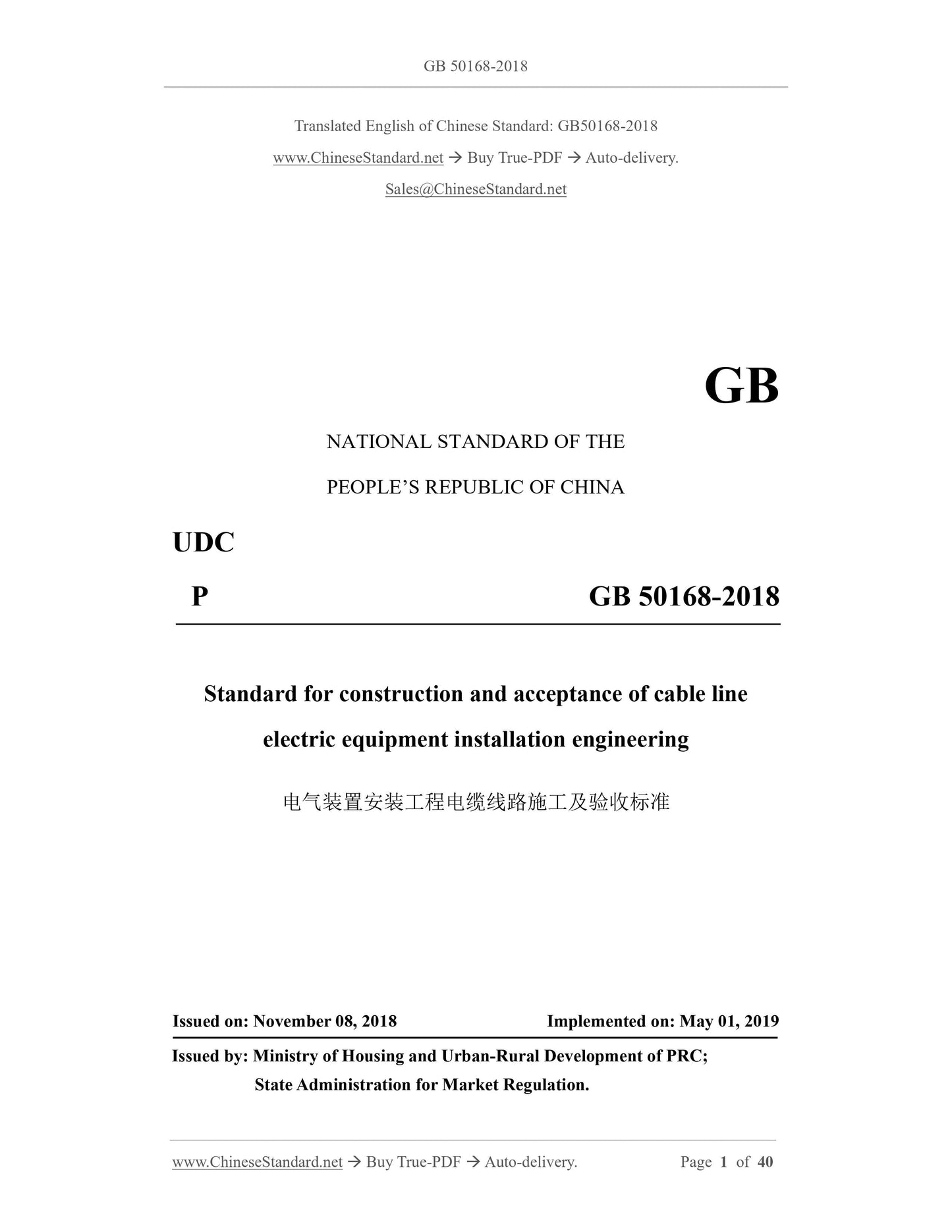
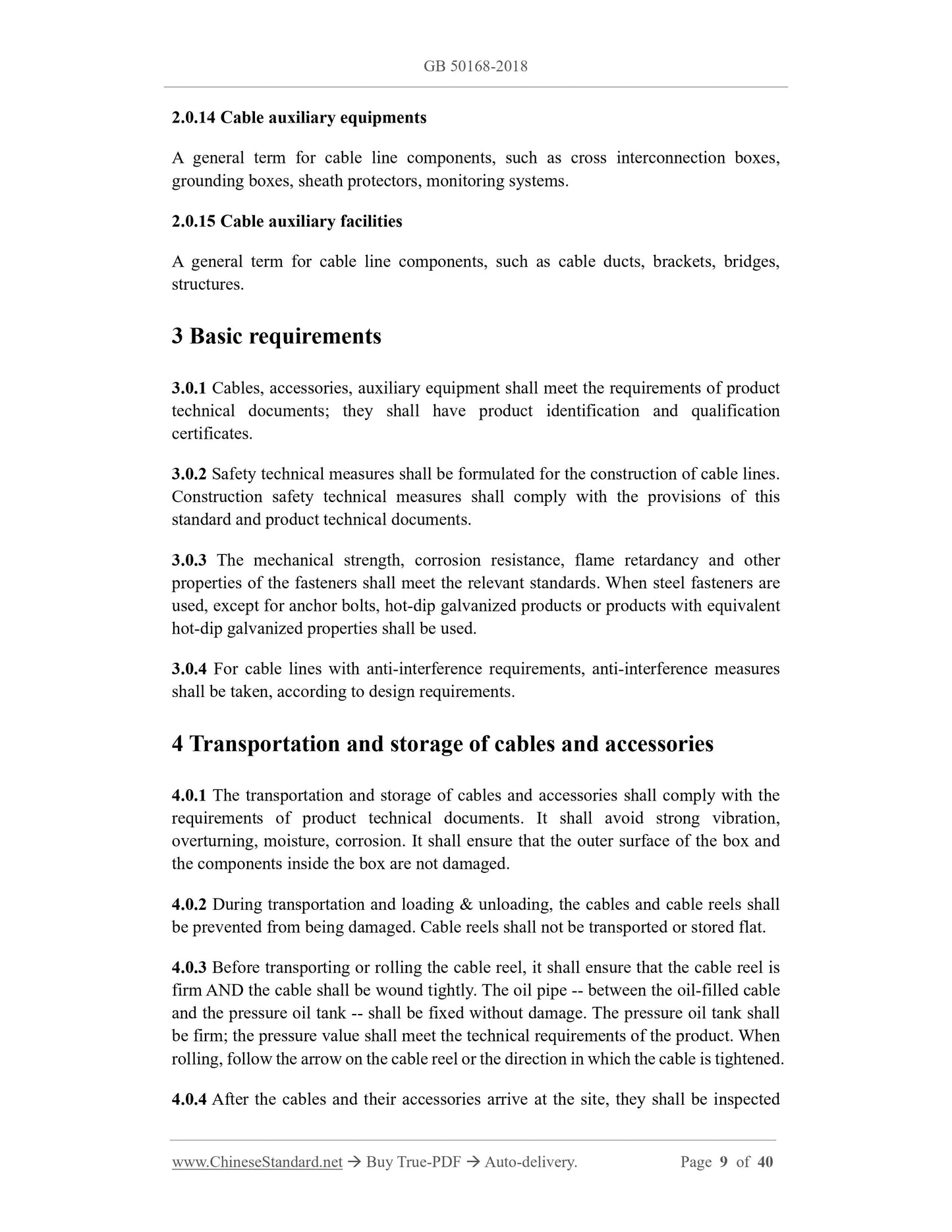
GB 50168-2018
GB
NATIONAL STANDARD OF THE
PEOPLE’S REPUBLIC OF CHINA
UDC
P GB 50168-2018
Standard for construction and acceptance of cable line
electric equipment installation engineering
ISSUED ON: NOVEMBER 08, 2018
IMPLEMENTED ON: MAY 01, 2019
Issued by: Ministry of Housing and Urban-Rural Development of PRC;
State Administration for Market Regulation.
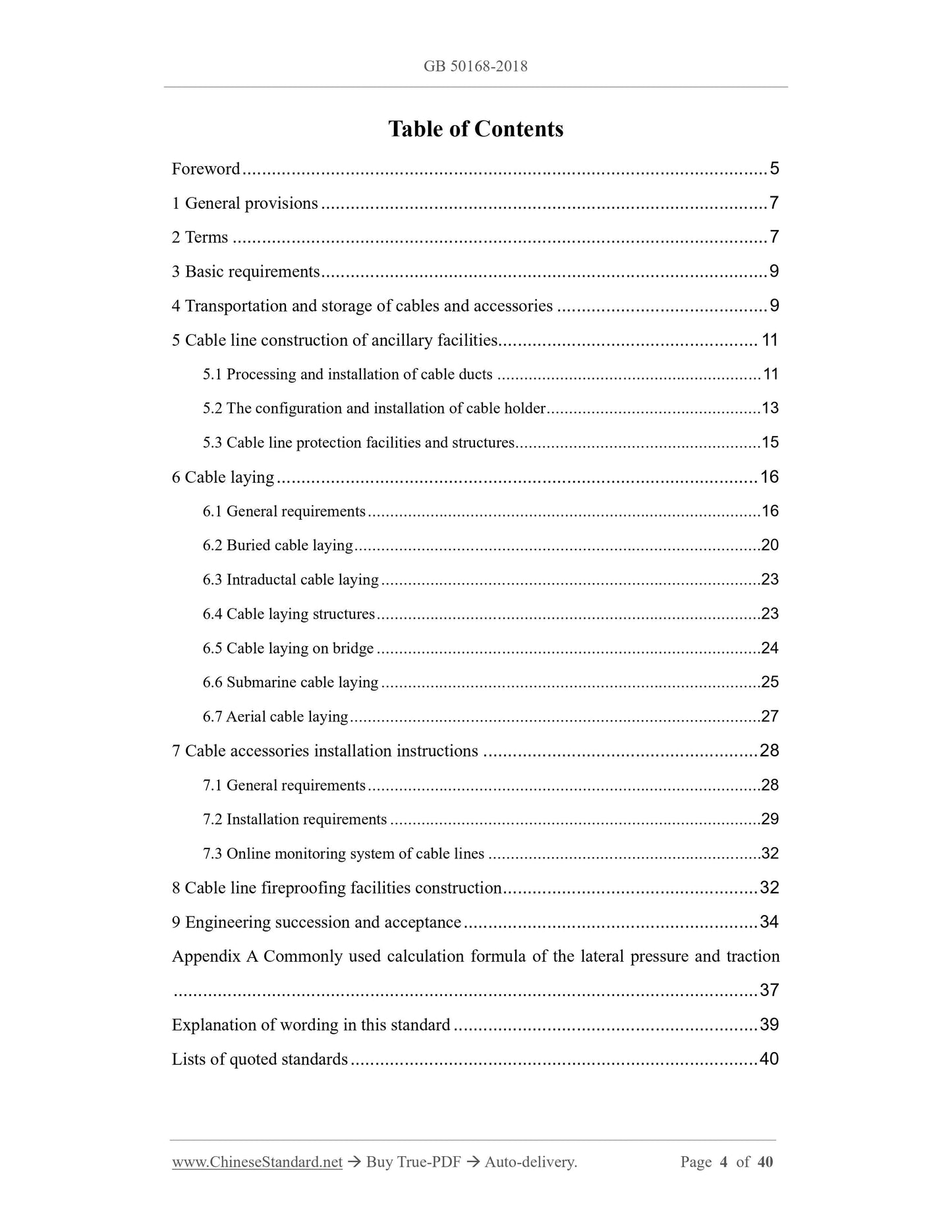
Table of Contents
Foreword ... 5
1 General provisions ... 7
2 Terms ... 7
3 Basic requirements ... 9
4 Transportation and storage of cables and accessories ... 9
5 Cable line construction of ancillary facilities... 11
5.1 Processing and installation of cable ducts ... 11
5.2 The configuration and installation of cable holder ... 13
5.3 Cable line protection facilities and structures ... 15
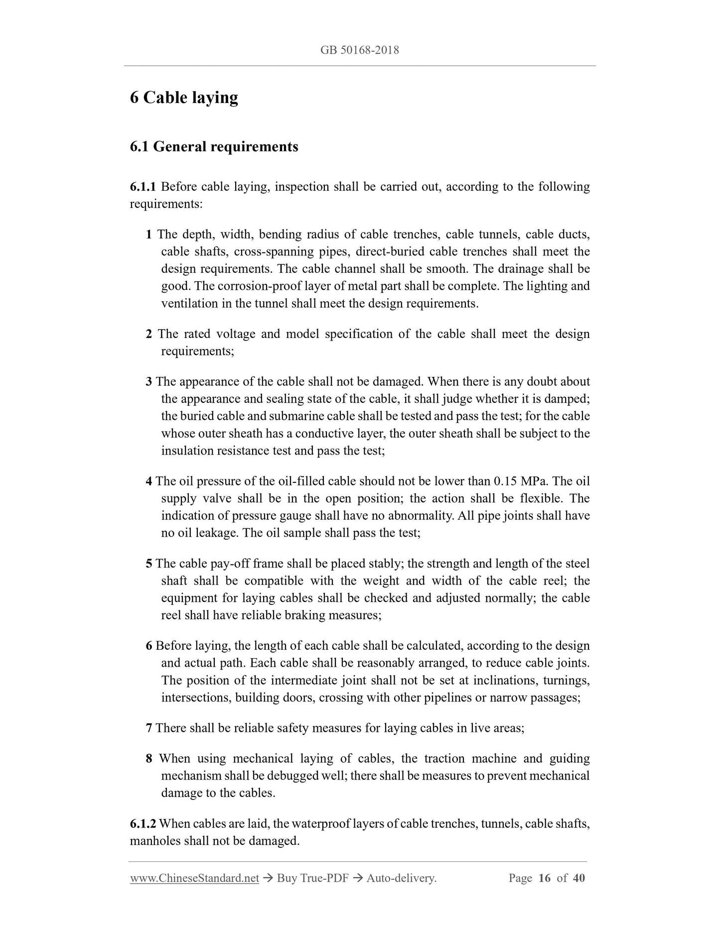
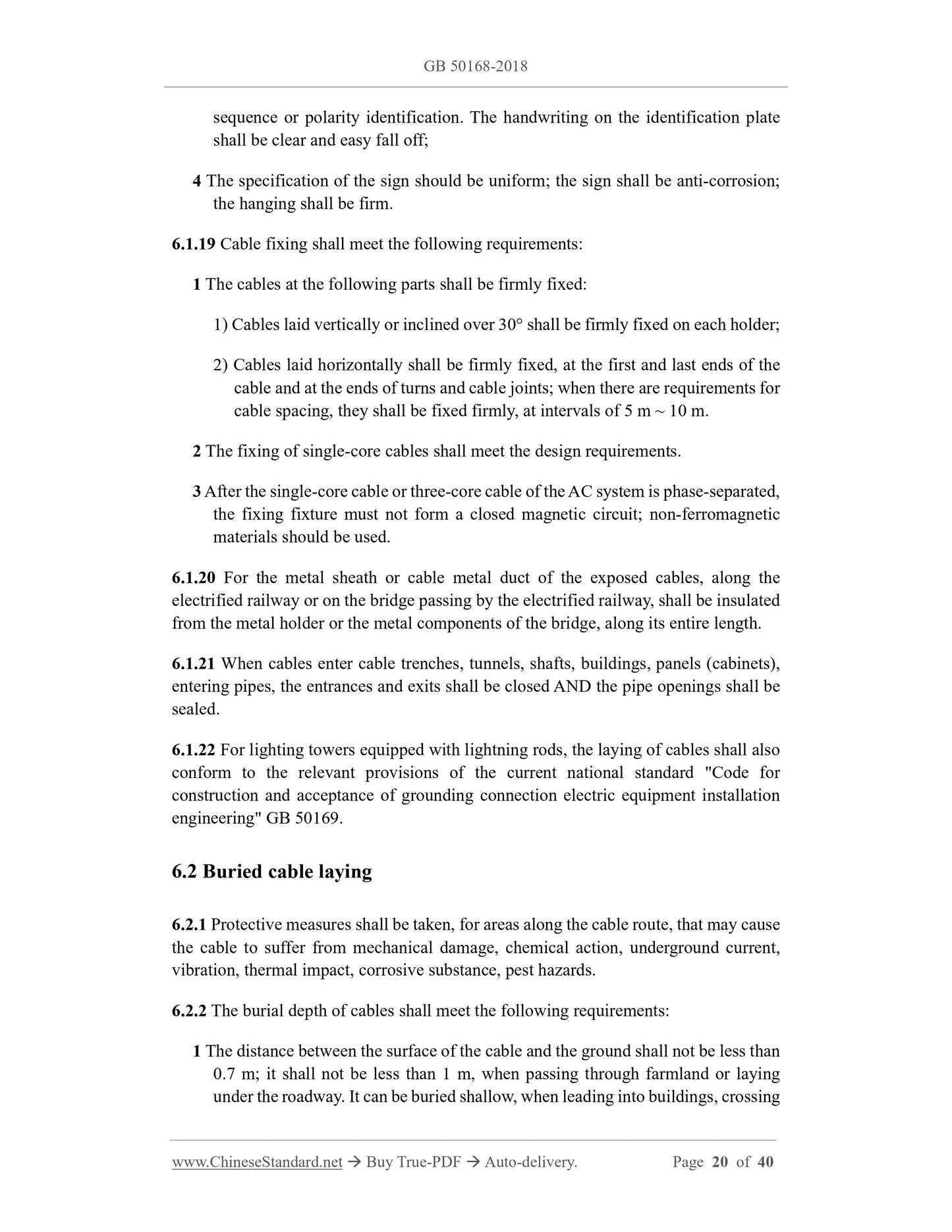
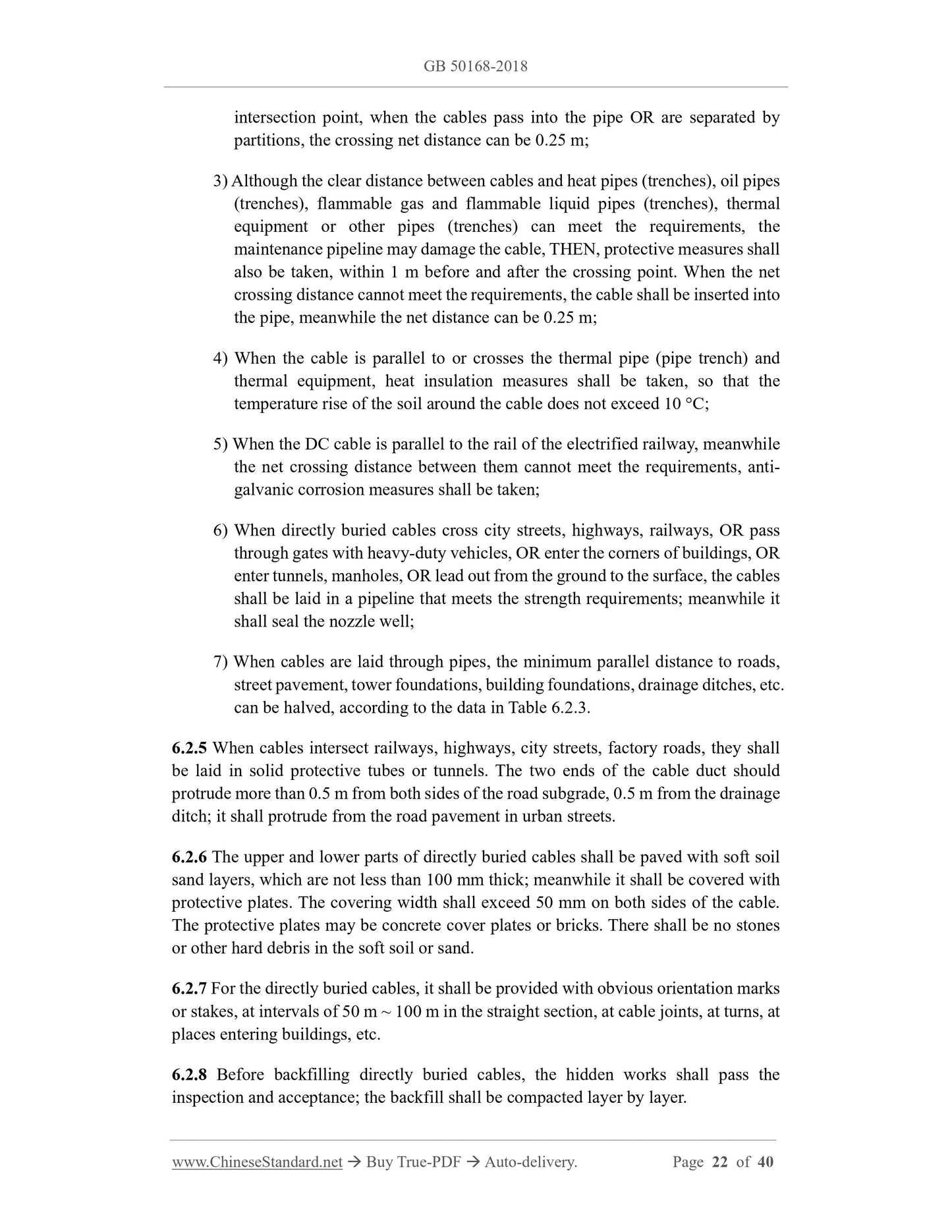
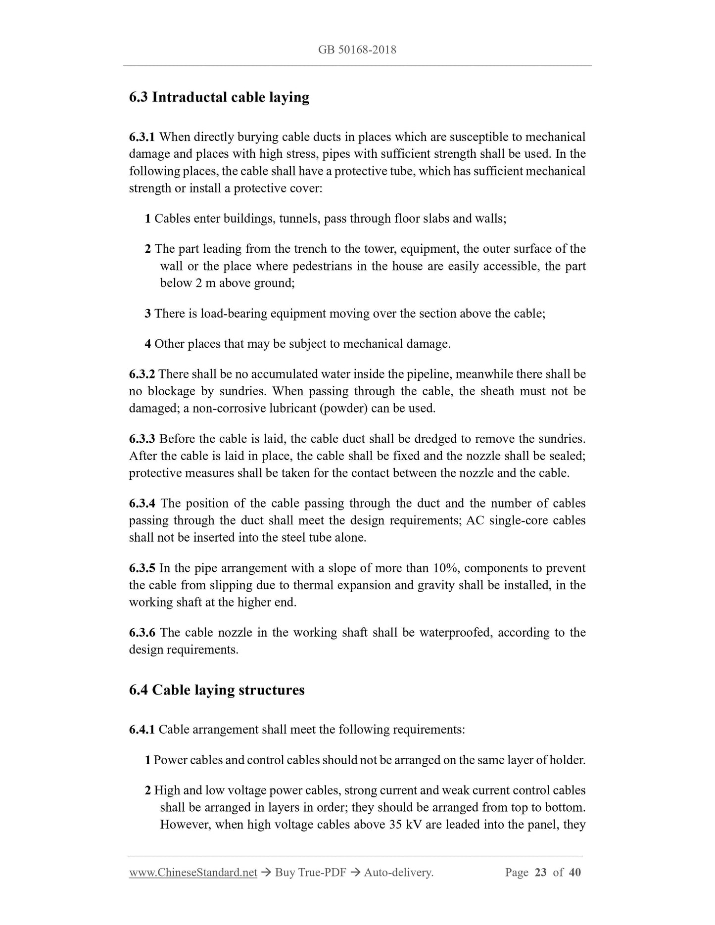
6 Cable laying ... 16
6.1 General requirements ... 16
6.2 Buried cable laying ... 20
6.3 Intraductal cable laying ... 23
6.4 Cable laying structures ... 23
6.5 Cable laying on bridge ... 24
6.6 Submarine cable laying ... 25
6.7 Aerial cable laying ... 27
7 Cable accessories installation instructions ... 28
7.1 General requirements ... 28
7.2 Installation requirements ... 29
7.3 Online monitoring system of cable lines ... 32
8 Cable line fireproofing facilities construction ... 32
9 Engineering succession and acceptance ... 34
Appendix A Commonly used calculation formula of the lateral pressure and traction
... 37
Explanation of wording in this standard ... 39
Lists of quoted standards ... 40
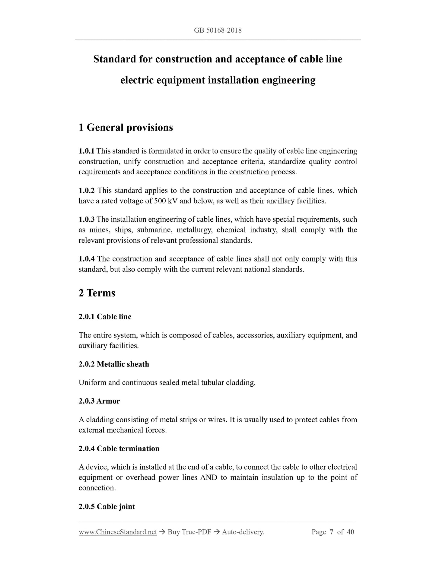
Standard for construction and acceptance of cable line
electric equipment installation engineering
1 General provisions
1.0.1 This standard is formulated in order to ensure the quality of cable line engineering
construction, unify construction and acceptance criteria, standardize quality control
requirements and acceptance conditions in the construction process.
1.0.2 This standard applies to the construction and acceptance of cable lines, which
have a rated voltage of 500 kV and below, as well as their ancillary facilities.
1.0.3 The installation engineering of cable lines, which have special requirements, such
as mines, ships, submarine, metallurgy, chemical industry, shall comply with the
relevant provisions of relevant professional standards.
1.0.4 The construction and acceptance of cable lines shall not only comply with this
standard, but also comply with the current relevant national standards.
2 Terms
2.0.1 Cable line
The entire system, which is composed of cables, accessories, auxiliary equipment, and
auxiliary facilities.
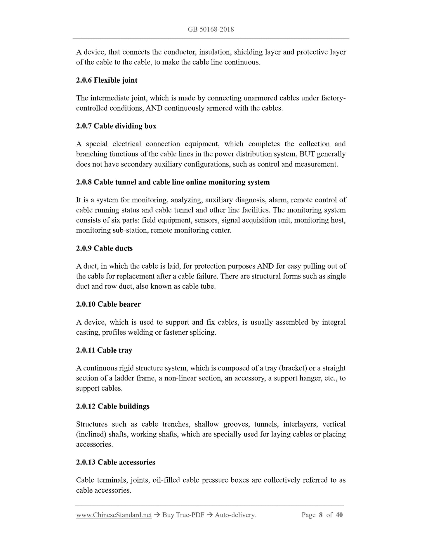
2.0.2 Metallic sheath
Uniform and continuous sealed metal tubular cladding.
2.0.3 Armor
A cladding consisting of metal strips or wires. It is usually used to protect cables from
external mechanical forces.
2.0.4 Cable termination
A device, which is installed at the end of a cable, to connect the cable to other electrical
equipment or overhead power lines AND to maintain insulation up to the point of
connection.
2.0.5 Cable joint
A device, that connects the conductor, insulation, shielding layer and protective layer
of the cable to the cable, to make the cable line continuous.
2.0.6 Flexible joint
The intermediate joint, which is made by connecting unarmored cables under factory-
controlled conditions, AND continuously armored with the cables.
2.0.7 Cable dividing box
A special electrical connection equipment, which completes the collection and
branching functions of the cable lines in the power distribution system, BUT generally
does not have secondary auxiliary configurations, such as control and measurement.
2.0.8 Cable tunnel and cable line online monitoring system
It is a system for monitoring, analyzing, auxiliary diagnosis, alarm, remote control of
cable running status and cable tunnel and other line facilities. The monitoring system
consists of six parts: field equipment, sensors, signal acquisition unit, monitoring host,
monitoring sub-station, remote monitoring center.
2.0.9 Cable ducts
A duct, in which the cable is laid, for protection purposes AND for easy pulling out of
the cable for replacement after a cable failure. There are structural forms such as single
duct and row duct, also known as cable tube.
2.0.10 Cable bearer
A device, which is used to support and fix cables, is usually assembled by integral
casting, profiles welding or fastener splicing.
2.0.11 Cable tray
A continuous rigid structure system, which is composed of a tray (bracket) or a straight
section of a ladder frame, a non-linear section, an accessory, a support hanger, etc., to
support cables.
2.0.12 Cable buildings
Structures such as cable trenches, shallow grooves, tunnels, interlayers, vertical
(inclined) shafts, working shafts, which are specially used for laying cables or placing
accessories.
2.0.13 Cable accessories
Cable terminals, joints, oil-filled cable pressure boxes are collectively referred to as
cable accessories.
2.0.14 Cable auxiliary equipments
A general term for cable line components, such as cross interconnection boxes,
grounding boxes, sheath protectors, monitoring systems.
2.0.15 Cable auxiliary facilities
A general term for cable line components, such as cable ducts, brackets, bridges,
structures.
3 Basic requirements
3.0.1 Cables, accessories, auxiliary equipment shall meet the requirements of product
technical documents; they shall have product identification and qualification
certificates.
3.0.2 Safety technical measures shall be formulated for the construction of cable lines.
Construction safety technical measures shall comply with the provisions of this
standard and product technical documents.
3.0.3 The mechanical strength, corrosion resistance, flame retardancy and other
properties of the fasteners shall meet the relevant standards. When steel fasteners are
used, except for anchor bolts, hot-dip galvanized products or products with equivalent
hot-dip galvanized properties shall be used.
3.0.4 For cable lines with anti-interference requirements, anti-interference measures
shall be taken, according to design requirements.
4 Transportation and storage of cables and accessories
4.0.1 The transportation and storage of cables and accessories shall comply with the
requirements of product technical documents. It shall avoid strong vibration,
overturning, moisture, corrosion. It shall ensure that the outer surface of the box and
the components inside the box are not damaged.
4.0.2 During transportation and loading and unloading, the cables and cable reels shall
be prevented from being damaged. Cable reels shall not be transported or stored flat.
4.0.3 Before transporting or rolling the cable reel, it shall ensure that the cable reel is
firm AND the cable shall be wound tightly. The oil pipe -- between the oil-filled cable
and the pressure oil tank -- shall be fixed without damage. The pressure oil tank shall
be firm; the pressure value shall meet the technical requirements of the product. When
rolling, follow the arrow on the cable reel or the direction in which the cable is tightened.
4.0.4 After the cables and their accessories arrive at the site, they shall be inspected
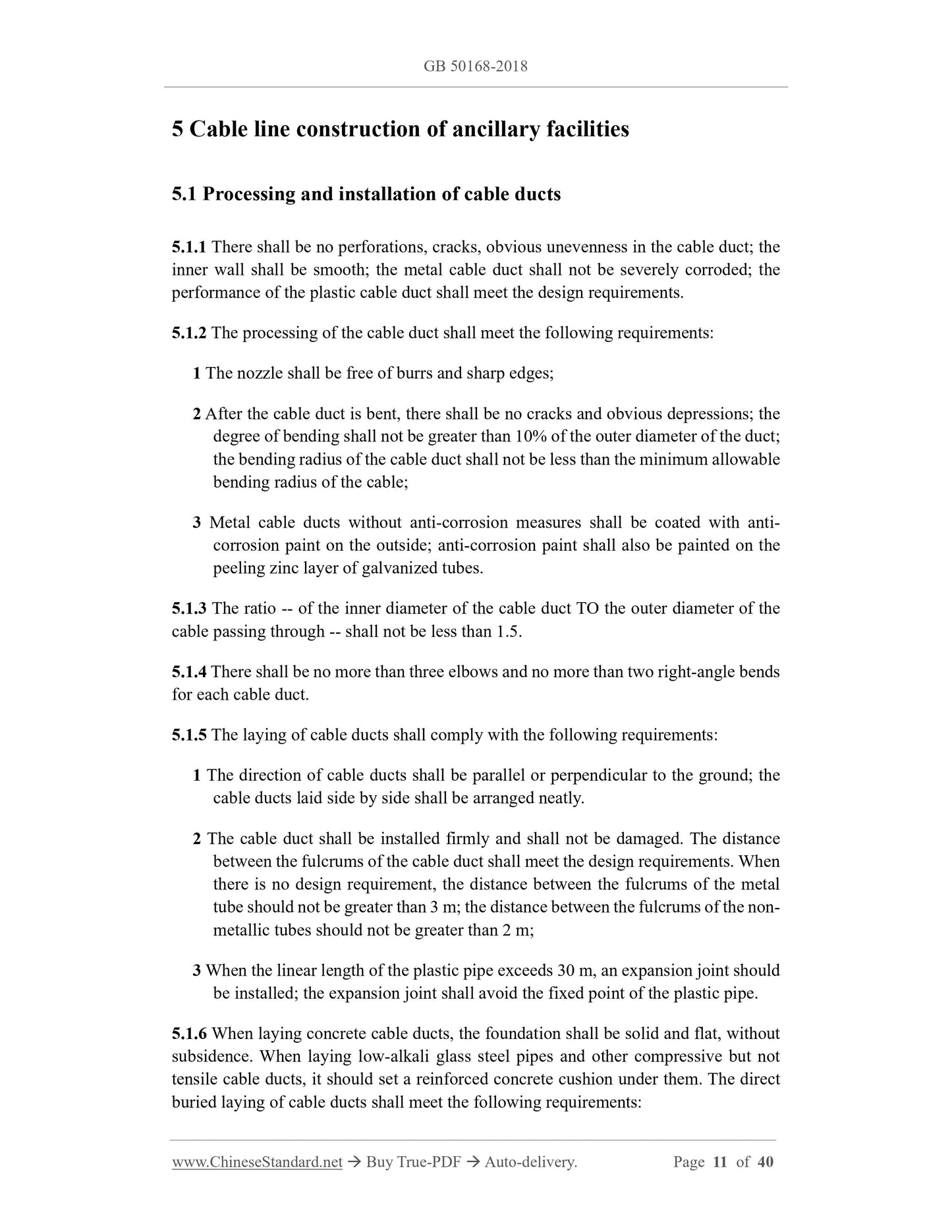
5 Cable line construction of ancillary facilities
5.1 Processing and installation of cable ducts
5.1.1 There shall be no perforations, cracks, obvious unevenness in the cable duct; the
inner wall shall be smooth; the metal cable duct shall not be severely corroded; the
performance of the plastic cable duct shall meet the design requirements.
5.1.2 The processing of the cable duct shall meet the following requirements:
1 The nozzle shall be free of burrs and sharp edges;
2 After the cable duct is bent, there shall be no cracks and obvious depressions; the
degree of bending shall not be greater than 10% of the outer diameter of the duct;
the bending radius of the cable duct shall not be less than the minimum allowable
bending radius of the cable;
3 Metal cable ducts without anti-corrosion measures shall be coated with anti-
corrosion paint on the outside; anti-corrosion paint shall also be painted on the
peeling zinc layer of galvanized tubes.
5.1.3 The ratio -- of the inner diameter of the cable duct TO the outer diameter of the
cable passing through -- shall not be less than 1.5.
5.1.4 There shall be no more than three elbows and no more than two right-angle bends
for each cable duct.
5.1.5 The laying of cable ducts shall comply with the following requirements:
1 The direction of cable ducts shall be parallel or perpendicular to the ground; the
cable ducts laid side by side shall be arranged neatly.
2 The cable duct shall be installed firmly and shall not be damaged. The distance
between the fulcrums of the cable duct shall meet the design requirements. When
there is no design requirement, the distance between the fulcrums of the metal
tube should not be greater than 3 m; the distance between the fulcrums of the non-
metallic tubes should not be greater than 2 m;
3 When the linear length of the plastic pipe exceeds 30 m, an expansion joint should
be installed; the expansion joint shall avoid the fixed point of the plastic pipe.
5.1.6 When laying concrete cable ducts, the foundation shall be solid and flat, without
subsidence. When laying low-alkali glass steel pipes and other compressive but not
tensile cable ducts, it should set a reinforced concrete cushion under them. The direct
buried laying of cable ducts shall meet the following requirements:
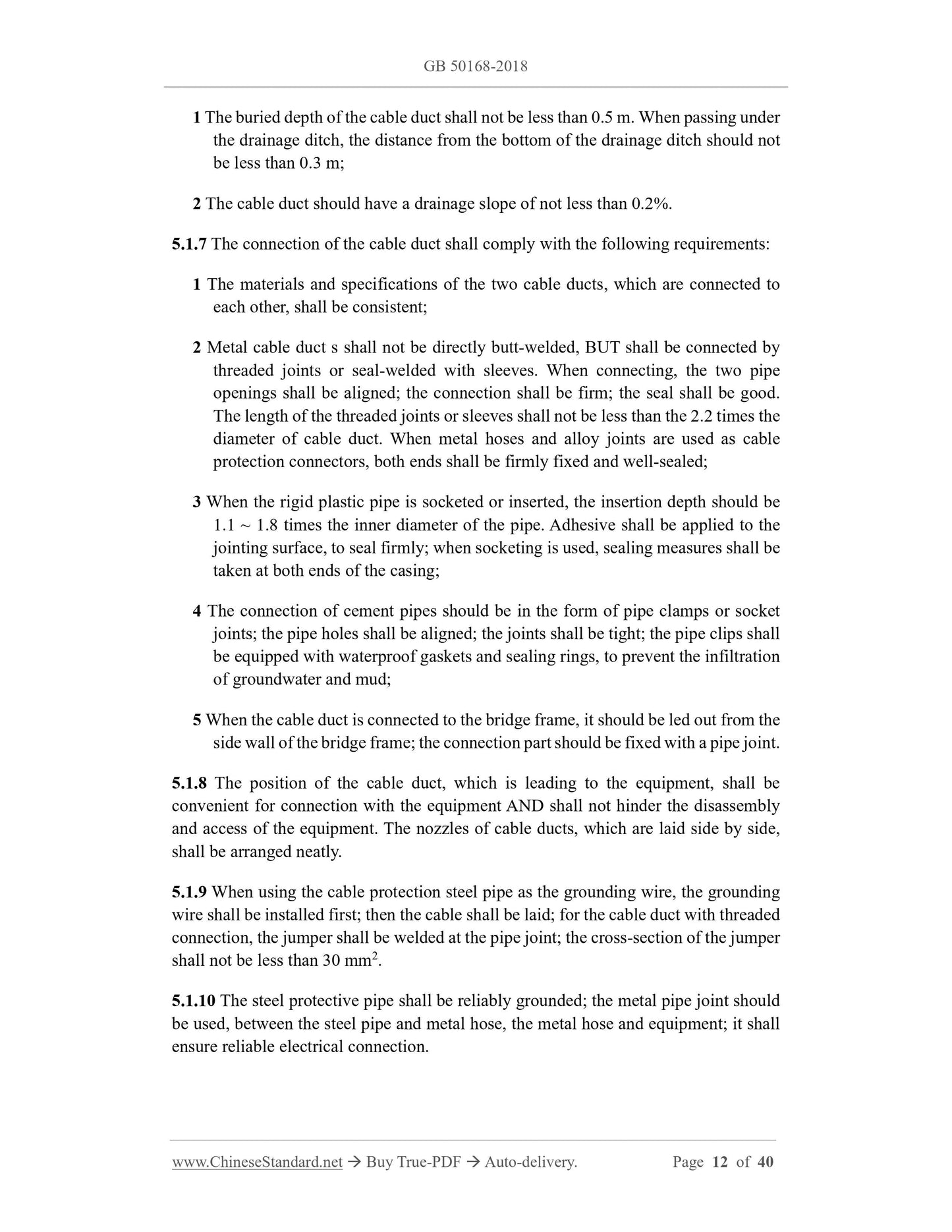
1 The buried depth of the cable duct shall not be less than 0.5 m. When passing under
the drainage ditch, the distance from the bottom of the drainage ditch should not
be less than 0.3 m;
2 The cable duct should have a drainage slope of not less than 0.2%.
5.1.7 The connection of the cable duct shall comply with the following requirements:
1 The materials and specifications of the two cable ducts, which are connected to
each other, shall be consistent;
2 Metal cable duct s shall not be directly butt-welded, BUT shall be connected by
threaded joints or seal-welded with sleeves. When connecting, the two pipe
openings shall be aligned; the connection shall be firm; the seal shall be good.
The length of the threaded joints or sleeves shall not be less than the 2.2 times the
diameter of cable duct. When metal hoses and alloy joints are used as cable
protection connectors, both ends shall be firmly fixed and well-sealed;
3 When the rigid plastic pipe is socketed or inserted, the insertion depth should be
1.1 ~ 1.8 times the inner diameter of the pipe. Adhesive shall be applied to the
jointing surface, to seal firmly; when socketing is used, sealing measures shall be
taken at both ends of the casing;
4 The connection of cement pipes should be in the form of pipe clamps or socket
joints; the pipe holes shall be aligned; the joints shall be tight; the pipe clips shall
be equipped with waterproof gaskets and sealing rings, to prevent the infiltration
of groundwater and mud;
5 When the cable duct is connected to the bridge frame, it should be led out from the
side wall of the bridge frame; the connection part should be fixed with a pipe joint.
5.1.8 The position of the cable duct, which is leading to the equipment, shall be
convenient for connection with the equipment AND shall not hinder the disassembly
and access of the equipment. The nozzles of cable ducts, which are laid side by side,
shall be arranged neatly.
5.1.9 When using the cable protection steel pipe as the grounding wire, the grounding
wire shall be installed first; then the cable shall be laid; for the cable duct with threaded
connection, the jumper shall be welded at the pipe joint; the cross-section of the jumper
shall not be less than 30 mm2.
5.1.10 The steel protective pipe shall be reliably grounded; the metal pipe joint should
be used, between the steel pipe and metal hose, the metal hose and equipment; it shall
ensure reliable electrical connection.
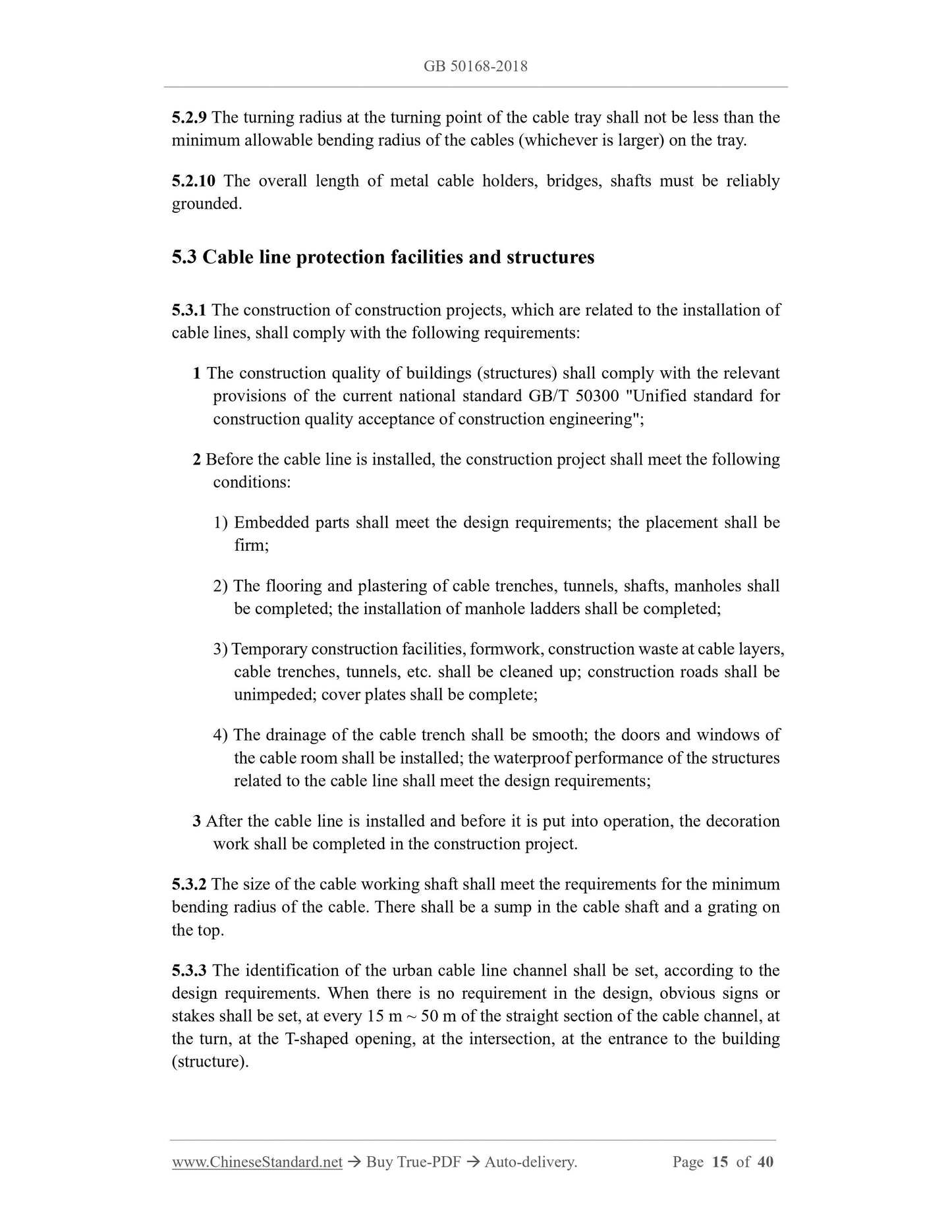
5.2.9 The turning radius at the turning point of the cable tray shall not be less than the
minimum allowable bending radius of the cables (whichever is larger) on the tray.
5.2.10 The overall length of metal cable holders, bridges, shafts must be reliably
grounded.
5.3 Cable line protection facilities and structures
5.3.1 The construction of construction projects, which are related to the installation of
cable lines, shall comply with the following requirements:
1 The construction quality of buildings (structures) shall comply with the relevant
provisions of the current national standard GB/T 50300 "Unified standard for
construction quality acceptance of construction engineering";
2 Before the cable line is installed, the construction project shall meet the following
conditions:
1) Embedded parts shall meet the design requirements; the placement shall be
firm;
2) The flooring and plastering of cable trenches, tunnels, shafts, manholes shall
be completed; the installation of manhole ladders shall be completed;
3) Temporary construction facilities, formwork, construction waste at cable layers,
cable trenches, tunnels, etc. shall be cleaned up; construction roads shall be
unimpeded; cover plates shall be complete;
4) The drainage of the cable trench shall be smooth; the doors and windows of
the cable room shall be installed; the waterproof performance of the structures
related to the cable line shall meet the design requirements;
3 After the cable line is installed and before it is put into operation, the decoration
work shall be completed in the construction project.
5.3.2 The size of the cable working shaft shall meet the requirements for the minimum
bending radius of the cable. There shall be a sump in the cable shaft and a grating on
the top.
5.3.3 The identification of the urban cable line channel shall be set, according to the
design requirements. When there is no requirement in the design, obvious signs or
stakes shall be set, at every 15 m ~ 50 m of the straight section of the cable channel, at
the turn, at the T-shaped opening, ...
Share