Skip to product information
1 of 10

www.ChineseStandard.us -- Field Test Asia Pte. Ltd.

GB 50111-2009 English PDF

GB 50111-2009 English PDF

Regular price $205.00
Regular price Sale price $205.00
Sale Sold out
Shipping calculated at checkout.
GB 50111-2009: [2009 Edition of GB 50111-2006] Code for seismic design of railway engineering
Delivery: 9 seconds. Download (& Email) true-PDF + Invoice.
Get Quotation: Click GB 50111-2009 (Self-service in 1-minute)
Historical versions (Master-website): GB 50111-2009
Preview True-PDF (Reload/Scroll-down if blank)

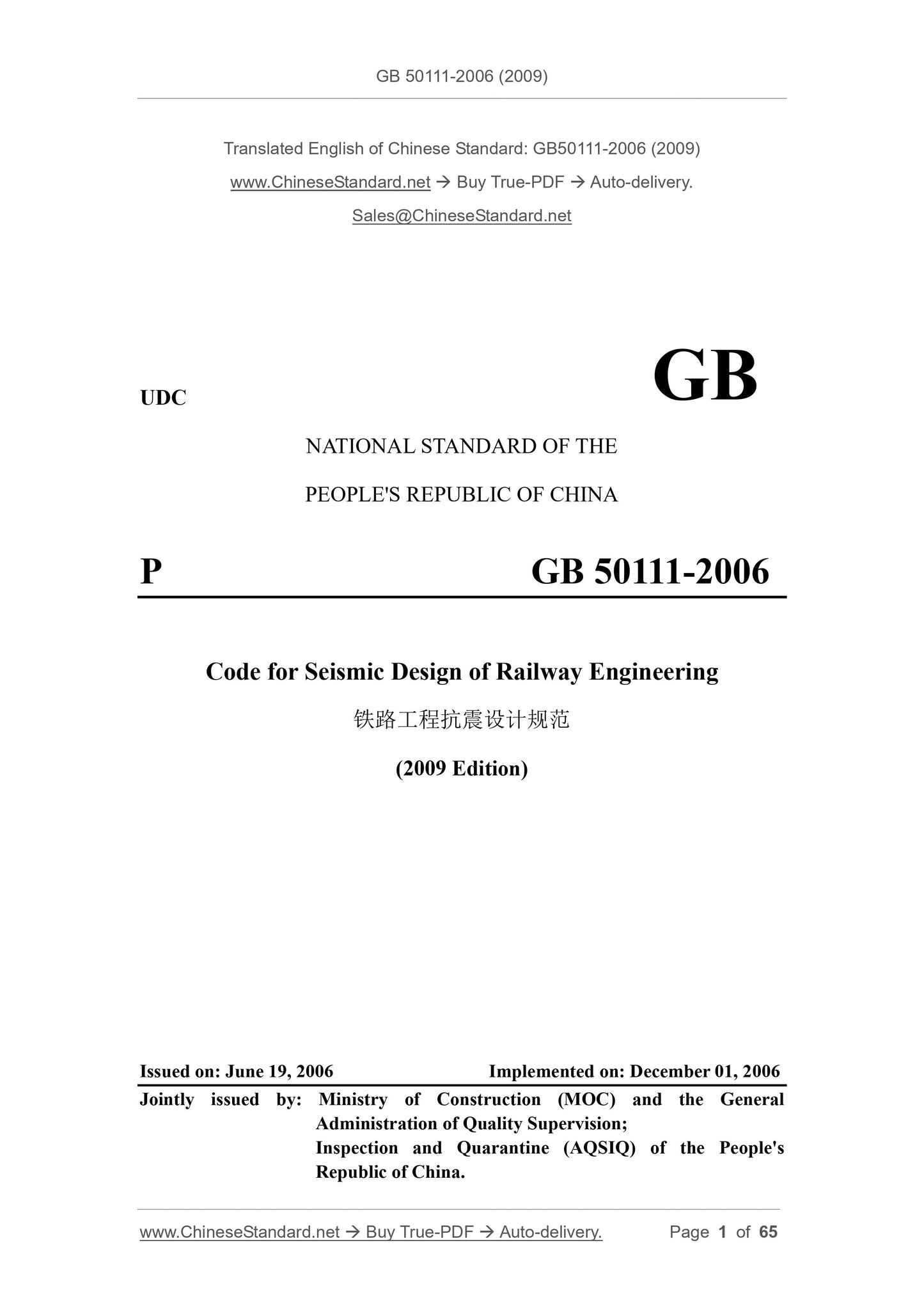
GB 50111-2006 (2009)
UDC
NATIONAL STANDARD OF THE
PEOPLE'S REPUBLIC OF CHINA
P GB 50111-2006
Code for Seismic Design of Railway Engineering
(2009 Edition)
ISSUED ON: JUNE 19, 2006
IMPLEMENTED ON: DECEMBER 01, 2006
Jointly issued by: Ministry of Construction (MOC) and the General
Administration of Quality Supervision;
Inspection and Quarantine (AQSIQ) of the People's
Republic of China.
GB
Table of Contents
1 General Provisions ... 9 
2 Terms and Symbols ... 9 
2.1 Terms ... 9 
2.2 Symbols ... 10 
3 Basic Requirements of Seismic Design ... 11 
4 Site and Foundation ... 15 
5 Route ... 18 
6 Subgrade ... 18 
6.1 Checking of Seismic Strength and Stability ... 18 
6.2 Seismic Measures ... 27 
7 Bridge ... 29 
7.1 General Requirements ... 29 
7.2 Seismic Analysis Method of Pier ... 31 
7.3 Ductility Design of Reinforced Concrete Bridge Pier ... 38 
7.4 Support and Abutment ... 39 
7.5 Seismic Measures ... 40 
8 Tunnel ... 44 
8.1 Checking of Seismic Strength and Stability ... 44 
8.2 Seismic Measures ... 46 
Appendix A Shear Wave Velocity Value of Different Rock and Soil ... 48 
Appendix B Test Methods of Liquefied Soil Determination ... 49 
Appendix C Reduction Coefficient of Mechanical Indexes of Liquefied Soil ... 51 
Appendix D Natural Vibration Performance Calculation of Beam Bridge Pier ... 52 
Appendix E Simplified Method for Seismic Calculation of Beam Bridge Pier under
Low-level Earthquake ... 55 
Appendix F Simplified Calculation Method for Ductility Design of Reinforced Concrete
Pier under High-level Earthquake ... 62 
Explanation of Wording in This Code ... 65 
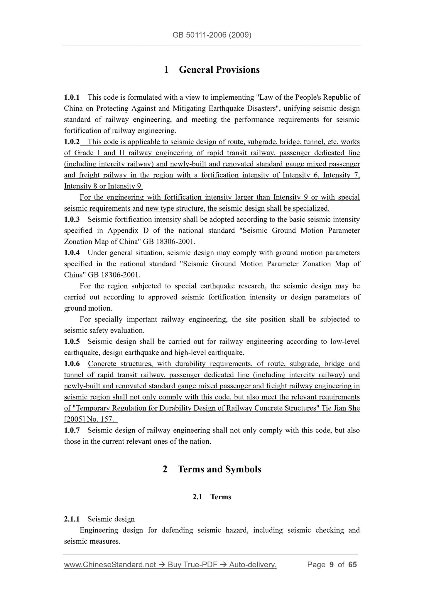
1 General Provisions
1.0.1 This code is formulated with a view to implementing "Law of the People's Republic of
China on Protecting Against and Mitigating Earthquake Disasters", unifying seismic design
standard of railway engineering, and meeting the performance requirements for seismic
fortification of railway engineering.
1.0.2 This code is applicable to seismic design of route, subgrade, bridge, tunnel, etc. works
of Grade I and II railway engineering of rapid transit railway, passenger dedicated line
(including intercity railway) and newly-built and renovated standard gauge mixed passenger
and freight railway in the region with a fortification intensity of Intensity 6, Intensity 7,
Intensity 8 or Intensity 9.
For the engineering with fortification intensity larger than Intensity 9 or with special
seismic requirements and new type structure, the seismic design shall be specialized.
1.0.3 Seismic fortification intensity shall be adopted according to the basic seismic intensity
specified in Appendix D of the national standard "Seismic Ground Motion Parameter
Zonation Map of China" GB 18306-2001.
1.0.4 Under general situation, seismic design may comply with ground motion parameters
specified in the national standard "Seismic Ground Motion Parameter Zonation Map of
China" GB 18306-2001.
For the region subjected to special earthquake research, the seismic design may be
carried out according to approved seismic fortification intensity or design parameters of
ground motion.
For specially important railway engineering, the site position shall be subjected to
seismic safety evaluation.
1.0.5 Seismic design shall be carried out for railway engineering according to low-level
earthquake, design earthquake and high-level earthquake.
1.0.6 Concrete structures, with durability requirements, of route, subgrade, bridge and
tunnel of rapid transit railway, passenger dedicated line (including intercity railway) and
newly-built and renovated standard gauge mixed passenger and freight railway engineering in
seismic region shall not only comply with this code, but also meet the relevant requirements
of "Temporary Regulation for Durability Design of Railway Concrete Structures" Tie Jian She
[2005] No. 157.
1.0.7 Seismic design of railway engineering shall not only comply with this code, but also
those in the current relevant ones of the nation.
2 Terms and Symbols
2.1 Terms
2.1.1 Seismic design
Engineering design for defending seismic hazard, including seismic checking and
seismic measures.
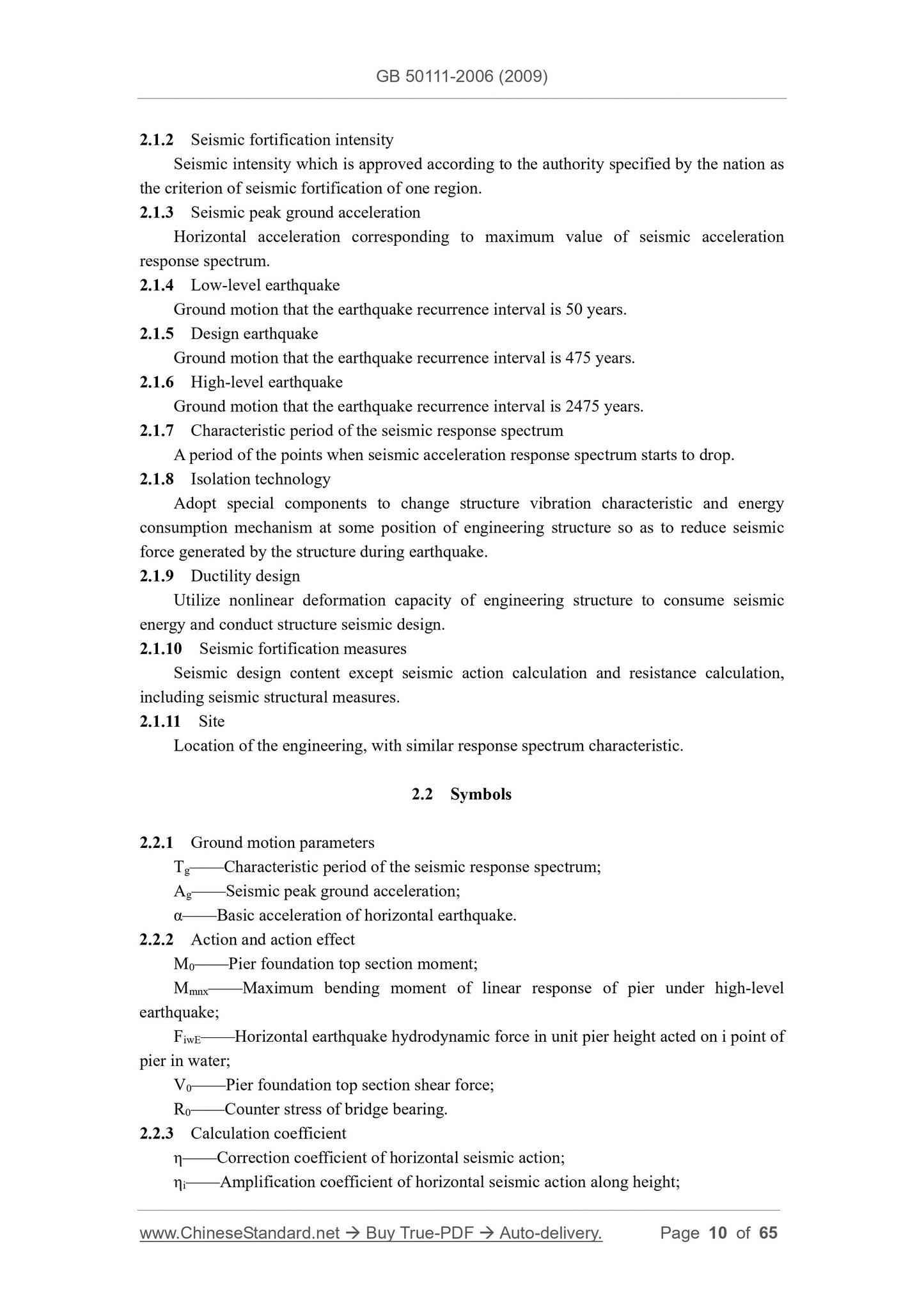
2.1.2 Seismic fortification intensity
Seismic intensity which is approved according to the authority specified by the nation as
the criterion of seismic fortification of one region.
2.1.3 Seismic peak ground acceleration
Horizontal acceleration corresponding to maximum value of seismic acceleration
response spectrum.
2.1.4 Low-level earthquake
Ground motion that the earthquake recurrence interval is 50 years.
2.1.5 Design earthquake
Ground motion that the earthquake recurrence interval is 475 years.
2.1.6 High-level earthquake
Ground motion that the earthquake recurrence interval is 2475 years.
2.1.7 Characteristic period of the seismic response spectrum
A period of the points when seismic acceleration response spectrum starts to drop.
2.1.8 Isolation technology
Adopt special components to change structure vibration characteristic and energy
consumption mechanism at some position of engineering structure so as to reduce seismic
force generated by the structure during earthquake.
2.1.9 Ductility design
Utilize nonlinear deformation capacity of engineering structure to consume seismic
energy and conduct structure seismic design.
2.1.10 Seismic fortification measures
Seismic design content except seismic action calculation and resistance calculation,
including seismic structural measures.
2.1.11 Site
Location of the engineering, with similar response spectrum characteristic.
2.2 Symbols
2.2.1 Ground motion parameters
Tg——Characteristic period of the seismic response spectrum;
Ag——Seismic peak ground acceleration;
α——Basic acceleration of horizontal earthquake.
2.2.2 Action and action effect
M0——Pier foundation top section moment;
Mmnx——Maximum bending moment of linear response of pier under high-level
earthquake;
FiwE——Horizontal earthquake hydrodynamic force in unit pier height acted on i point of
pier in water;
V0——Pier foundation top section shear force;
R0——Counter stress of bridge bearing.
2.2.3 Calculation coefficient
η——Correction coefficient of horizontal seismic action;
ηi——Amplification coefficient of horizontal seismic action along height;
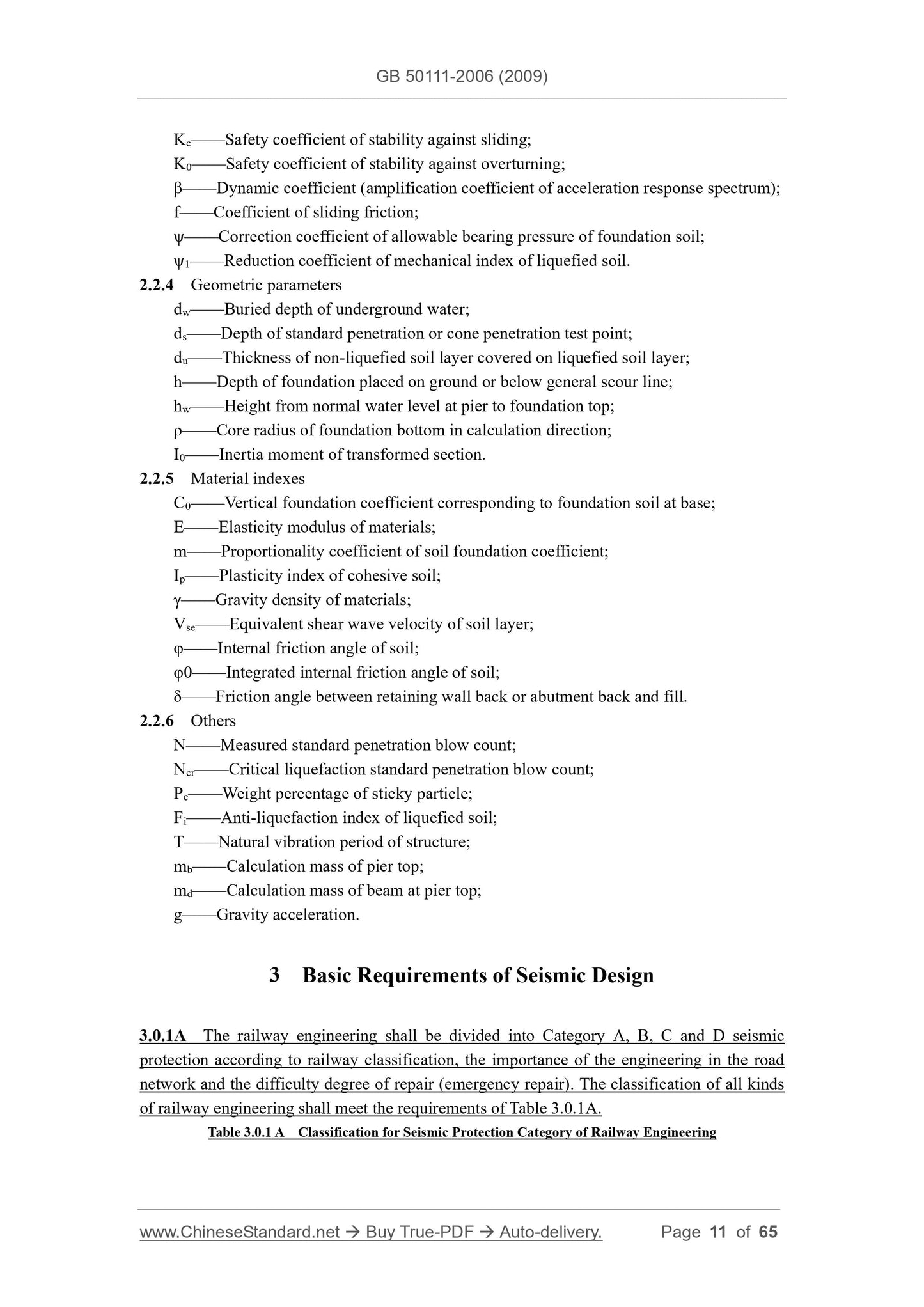
Kc——Safety coefficient of stability against sliding;
K0——Safety coefficient of stability against overturning;
β——Dynamic coefficient (amplification coefficient of acceleration response spectrum);
f——Coefficient of sliding friction;
ψ——Correction coefficient of allowable bearing pressure of foundation soil;
ψ1——Reduction coefficient of mechanical index of liquefied soil.
2.2.4 Geometric parameters
dw——Buried depth of underground water;
ds——Depth of standard penetration or cone penetration test point;
du——Thickness of non-liquefied soil layer covered on liquefied soil layer;
h——Depth of foundation placed on ground or below general scour line;
hw——Height from normal water level at pier to foundation top;
ρ——Core radius of foundation bottom in calculation direction;
I0——Inertia moment of transformed section.
2.2.5 Material indexes
C0——Vertical foundation coefficient corresponding to foundation soil at base;
E——Elasticity modulus of materials;
m——Proportionality coefficient of soil foundation coefficient;
Ip——Plasticity index of cohesive soil;
γ——Gravity density of materials;
Vse——Equivalent shear wave velocity of soil layer;
φ——Internal friction angle of soil;
φ0——Integrated internal friction angle of soil;
δ——Friction angle between retaining wall back or abutment back and fill.
2.2.6 Others
N——Measured standard penetration blow count;
Ncr——Critical liquefaction standard penetration blow count;
Pc——Weight percentage of sticky particle;
Fi——Anti-liquefaction index of liquefied soil;
T——Natural vibration period of structure;
mb——Calculation mass of pier top;
md——Calculation mass of beam at pier top;
g——Gravity acceleration.
3 Basic Requirements of Seismic Design
3.0.1A The railway engineering shall be divided into Category A, B, C and D seismic
protection according to railway classification, the importance of the engineering in the road
network and the difficulty degree of repair (emergency repair). The classification of all kinds
of railway engineering shall meet the requirements of Table 3.0.1A.
Table 3.0.1 A Classification for Seismic Protection Category of Railway Engineering
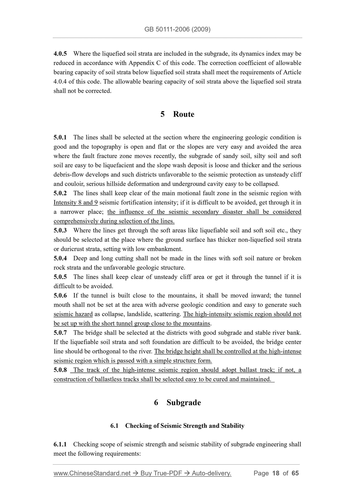
4.0.5 Where the liquefied soil strata are included in the subgrade, its dynamics index may be
reduced in accordance with Appendix C of this code. The correction coefficient of allowable
bearing capacity of soil strata below liquefied soil strata shall meet the requirements of Article
4.0.4 of this code. The allowable bearing capacity of soil strata above the liquefied soil strata
shall not be corrected.
5 Route
5.0.1 The lines shall be selected at the section where the engineering geologic condition is
good and the topography is open and flat or the slopes are very easy and avoided the area
where the fault fracture zone moves recently, the subgrade of sandy soil, silty soil and soft
soil are easy to be liquefacient and the slope wash deposit is loose and thicker and the serious
debris-flow develops and such districts unfavorable to the seismic protection as unsteady cliff
and couloir, serious hillside deformation and underground cavity easy to be collapsed.
5.0.2 The lines shall keep clear of the main motional fault zone in the seismic region with
Intensity 8 and 9 seismic fortification intensity; if it is difficult to be avoided, get through it in
a narrower place; the influence of the seismic secondary disaster shall be considered
comprehensively during selection of the lines.
5.0.3 Where the lines get through the soft areas like liquefiable soil and soft soil etc., they
should be selected at the place where the ground surface has thicker non-liquefied soil strata
or duricrust strata, setting with low embankment.
5.0.4 Deep and long cutting shall not be made in the lines with soft soil nature or broken
rock strata and the unfavorable geologic structure.
5.0.5 The lines shall keep clear of unsteady cliff area or get it through the tunnel if it is
difficult to be avoided.
5.0.6 If the tunnel is built close to the mountains, it shall be moved inward; the tunnel
mouth shall not be set at the area with adverse geologic condition and easy to generate such
seismic hazard as collapse, landslide, scattering. The high-intensity seismic region should not
be set up with the short tunnel group close to the mountains.
5.0.7 The bridge shall be selected at the districts with good subgrade and stable river bank.
If the liquefiable soil strata and soft foundation are difficult to be avoided, the bridge center
line should be orthogonal to the river. The bridge height shall be controlled at the high-intense
seismic region which is passed with a simple structure form.
5.0.8 The track of the high-intense seismic region should adopt ballast track; if not, a
construction of ballastless tracks shall be selected easy to be cured and maintained.
6 Subgrade
6.1 Checking of Seismic Strength and Stability
6.1.1 Checking scope of seismic strength and seismic stability of subgrade engineering shall
meet the following requirements:
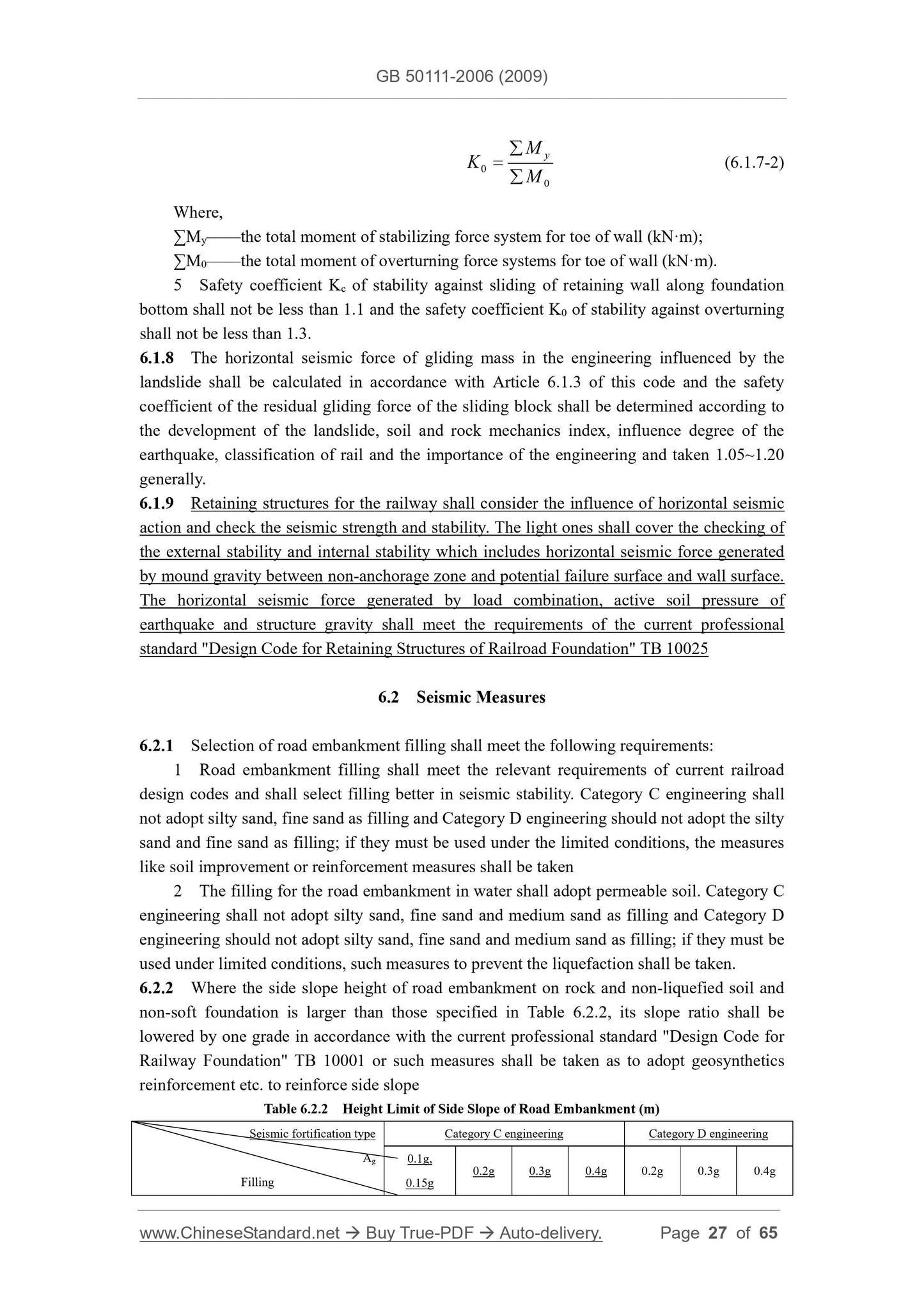
0 M
K y
 (6.1.7-2)
Where,
∑My——the total moment of stabilizing force system for toe of wall (kNꞏm);
∑M0——the total moment of overturning force systems for toe of wall (kNꞏm).
5 Safety coefficient Kc of stability against sliding of retaining wall along foundation
bottom shall not be less than 1.1 and the safety coefficient K0 of stability against overturning
shall not be less than 1.3.
6.1.8 The horizontal seismic force of gliding mass in the engineering influenced by the
landslide shall be calculated in accordance with Article 6.1.3 of this code and the safety
coefficient of the residual gliding force of the sliding block shall be determined according to
the development of the landslide, soil and rock mechanics index, influence degree of the
earthquake, classification of rail and the importance of the engineering and taken 1.05~1.20
generally.
6.1.9 Retaining structures for the railway shall consider the influence of horizontal seismic
action and check the seismic strength and stability. The light ones shall cover the checking of
the external stability and internal stability which includes horizontal seismic force generated
by mound gravity between non-anchorage zone and potential failure surface and wall surface.
The horizontal seismic force generated by load combination, active soil pressure of
earthquake and structure gravity shall meet the requirements of the current professional
standard "Design Code for Retaining Structures of Railroad Foundation" TB 10025
6.2 Seismic Measures
6.2.1 Selection of road embankment filling shall meet the following requirements:
1 Road embankment filling shall meet the relevant requirements of current railroad
design codes and shall select filling better in seismic stability. Category C engineering shall
not adopt silty sand, fine sand as filling and Category D engineering should not adopt the silty
sand and fine sand as filling; if they must be used under the limited conditions, the measures
like soil improvement or reinforcement measures shall be taken
2 The filling for the road embankment in water shall adopt permeable soil. Category C
engineering shall not adopt silty sand, fine sand and medium sand as filling and Category D
engineering should not adopt silty sand, fine sand and medium sand as filling; if they must be
used under limited conditions, such measures to prevent the liquefaction shall be taken.
6.2.2 Where the side slope height of road embankment on rock and non-liquefied soil and
non-soft foundation is larger than those specified in Table 6.2.2, its slope ratio shall be
lowered by one grade in accordance with the current professional standard "Design Code for
Railwa...
View full details