Skip to product information
1 of 6

PayPal, credit cards. Download editable-PDF and invoice in 1 second!

GB 26134-2024 English PDF (GB26134-2024)

GB 26134-2024 English PDF (GB26134-2024)

Regular price $215.00 USD
Regular price Sale price $215.00 USD
Sale Sold out
Shipping calculated at checkout.
Delivery: 3 seconds. Download true-PDF + Invoice.
Get Quotation: Click GB 26134-2024 (Self-service in 1-minute)
Historical versions (Master-website): GB 26134-2024
Preview True-PDF (Reload/Scroll-down if blank)

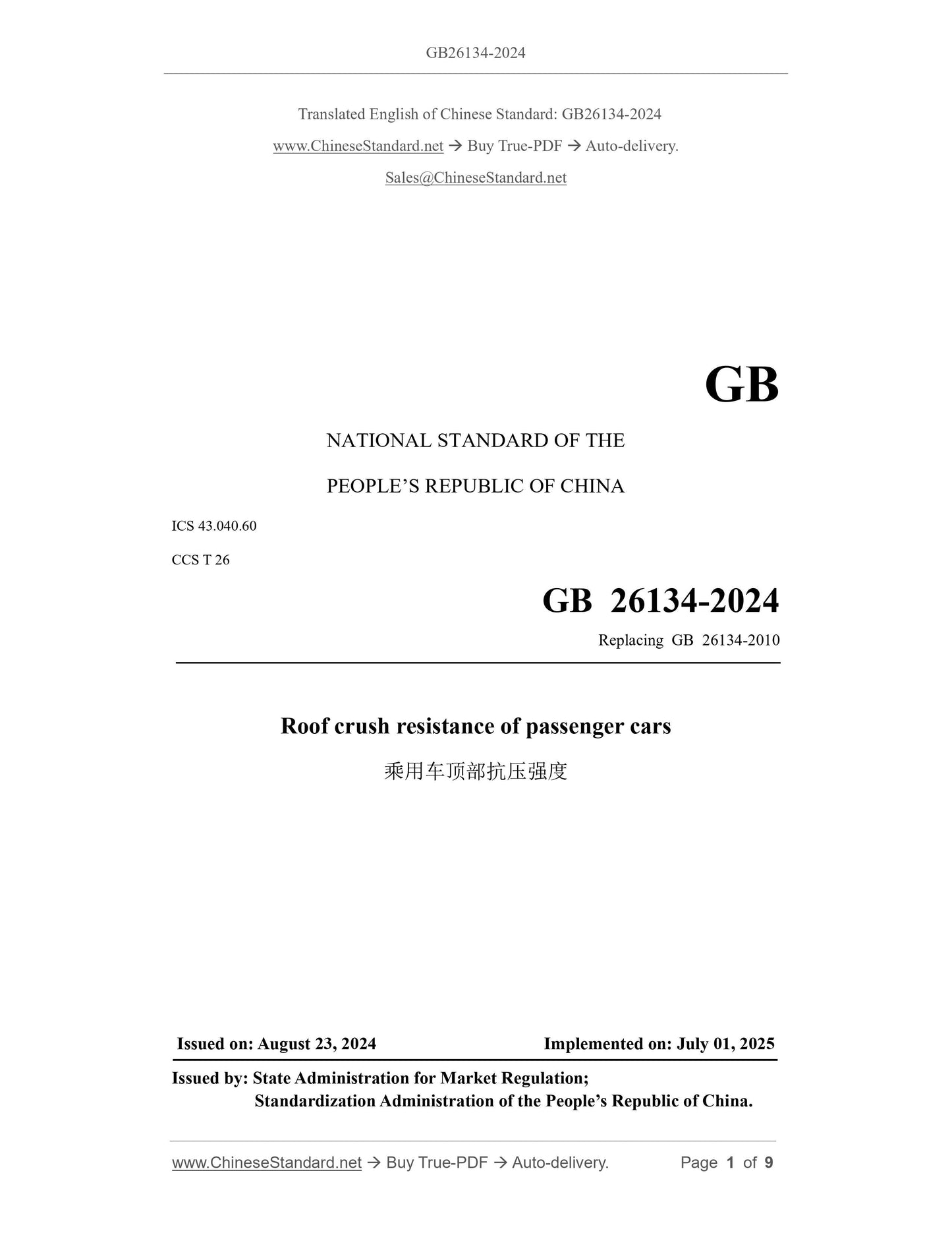
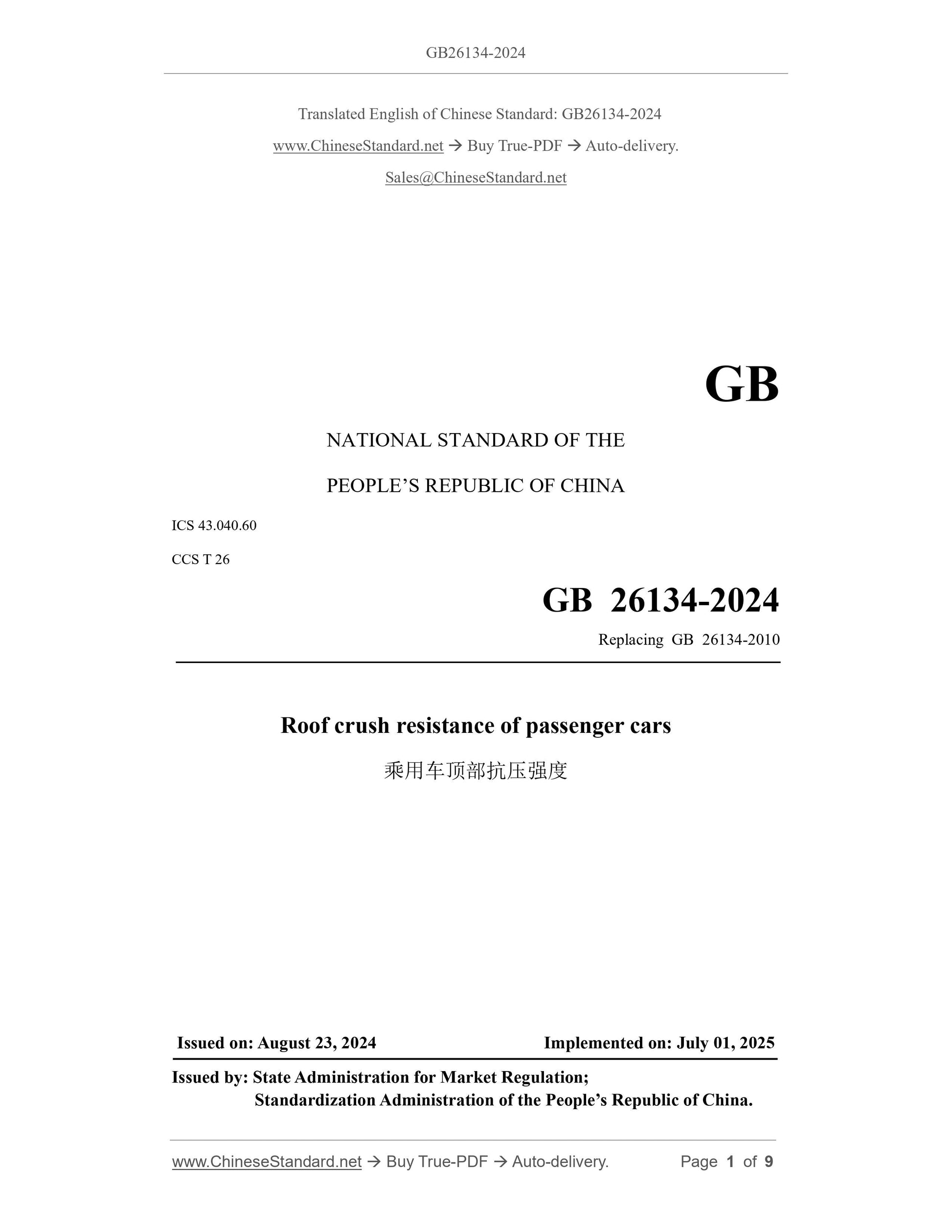
GB 26134-2024: Roof crush resistance of passenger cars
GB 26134-2024.Passenger car roof compressive strength
National Standard of the People's Republic of China
Replaces GB 26134-2010
Passenger car roof compressive strength
Released on 2024-08-23
2025-07-01 Implementation
State Administration for Market Regulation
The National Standardization Administration issued
Preface
This document is in accordance with the provisions of GB/T 1.1-2020 "Guidelines for standardization work Part 1.Structure and drafting rules for standardization documents"
Drafting.
This document replaces GB 26134-2010 "Compressive Strength of Passenger Car Roof". Compared with GB 26134-2010, except for structural adjustment and editing,
In addition to the changes in performance, the main technical changes are as follows.
--- Added the term "skylight" and its definition (see 3.1);
--- Changed the definition of the term "front windshield trim" (see 3.2, 2.4 of the.2010 edition);
--- Changed the vehicle applied load limit (see Chapter 4, Chapter 3 of the.2010 edition);
--- Added the force limit of the head model (see Chapter 4);
--- Added requirements for vehicle pitch angle during vehicle positioning (see 5.1);
--- Added the adjustment method of the front outer seats of the vehicle (see 5.2);
--- Added requirements for head models (see 5.3);
--- Added the same type determination (see Chapter 6);
--- Increased the implementation of the standard (see Chapter 7).
Please note that some of the contents of this document may involve patents. The issuing organization of this document does not assume the responsibility for identifying patents.
This document is proposed and coordinated by the Ministry of Industry and Information Technology of the People's Republic of China.
This document was first published in.2010 and this is the first revision.
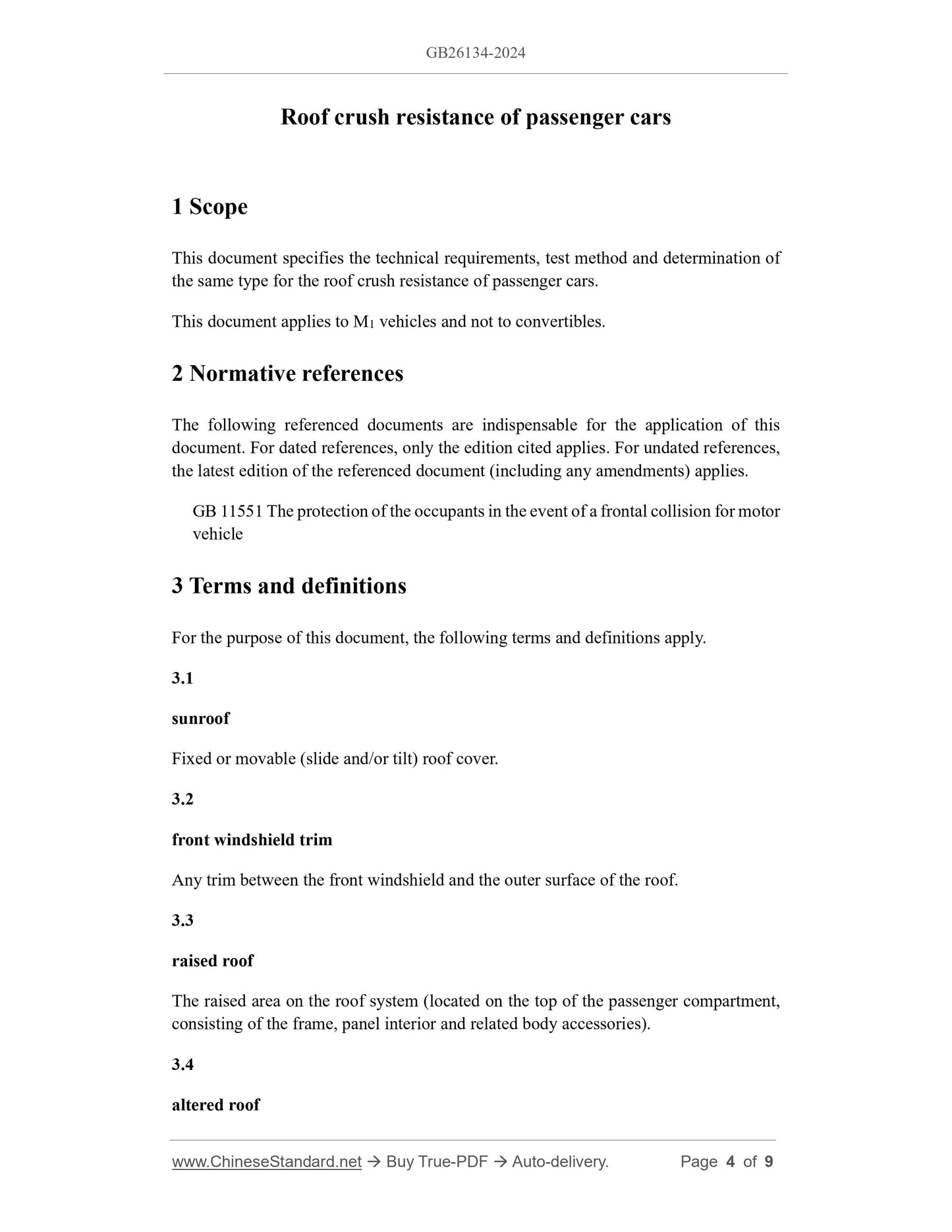
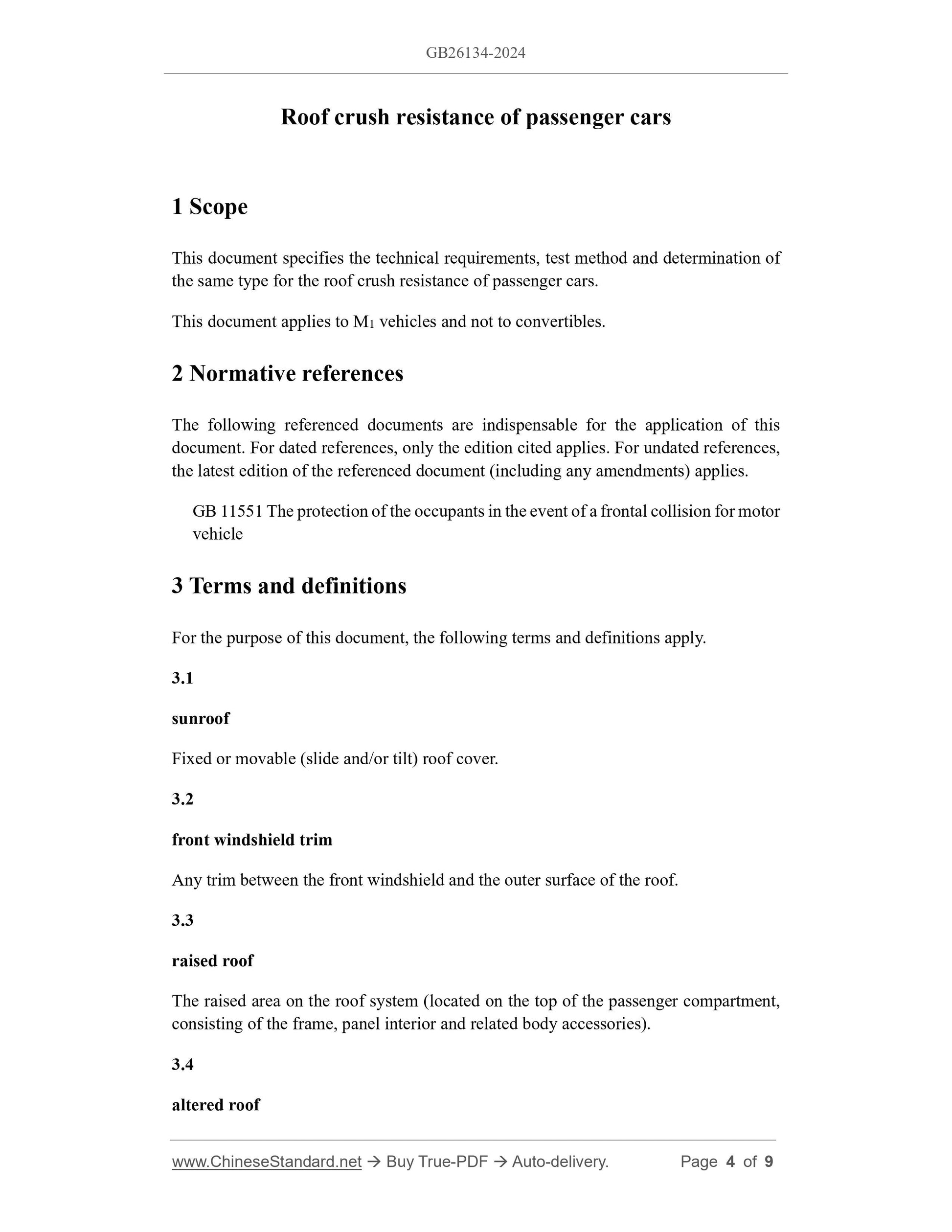
1 Scope
This document specifies the technical requirements, test methods and identification of the same type for the compressive strength of the roof of passenger cars.
This document applies to M1 category vehicles and not to convertibles.
2 Normative references
The contents of the following documents constitute essential clauses of this document through normative references in this document.
For referenced documents without a date, only the version corresponding to that date applies to this document; for referenced documents without a date, the latest version (including all amendments) applies to
This document.
GB 11551 Occupant protection in frontal collision of motor vehicles
3 Terms and definitions
The following terms and definitions apply to this document.
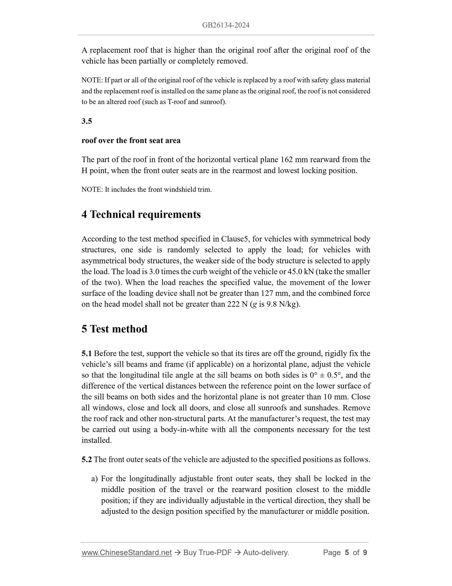
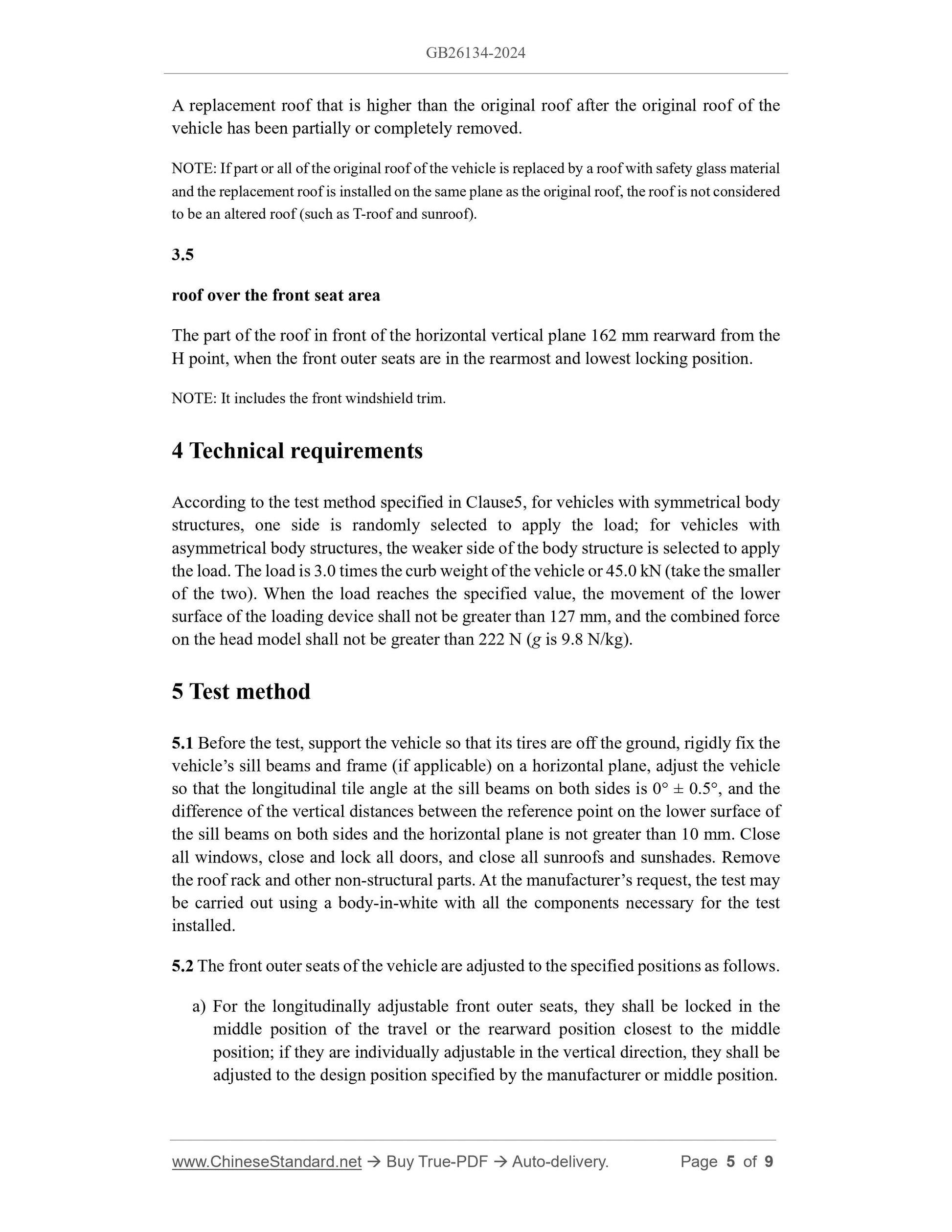
4 Technical requirements
According to the test method specified in Chapter 5, for vehicles with symmetrical body structures, one side is randomly selected to apply load; for vehicles with uneven body structures,
For symmetrical vehicles, select the weaker side of the vehicle body structure to apply the load. The load is 3.0 times the vehicle curb weight or 45.0 kN (whichever is smaller).
When the load reaches the specified value, the movement of the lower surface of the loading device should not exceed 127 mm, and the resultant force on the head model should not exceed
222N (9.8N/kg for g).
5 Test methods
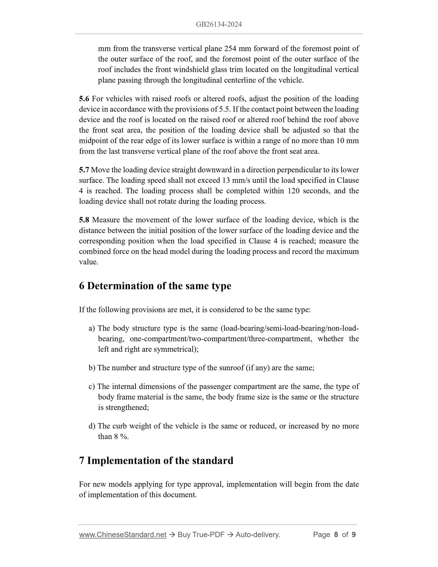
5.1 Before the test, support the vehicle so that its tires are off the ground, rigidly fix the vehicle sill beam and frame (if applicable) on a horizontal surface, and adjust the vehicle
The vehicle is set so that the longitudinal pitch angle at the sill beams on both sides is 0°±0.5°, and the vertical distance between the reference point on the lower surface of the sill beams on both sides and the horizontal plane is
The difference is no more than 10mm. Close all windows, close and lock all doors, close all sunroofs and sunshades. Remove the roof rack.
and other non-structural parts. At the manufacturer's request, the body-in-white may be used for the test with all the components necessary for the test installed.
5.2 The outer front seats of the vehicle should be adjusted to the specified positions as follows.
a) For the front outboard seats which are longitudinally adjustable, they should be in the middle position of their travel or in the rearward position closest to the middle position.
If it can be adjusted independently in the vertical direction, it should be adjusted to the design position or intermediate position specified by the manufacturer.
b) Adjust the seat back to the design position specified by the manufacturer. If no position is specified, adjust the seat back to the position from the vertical plane.
25° backward tilt position.
c) Place any adjustable head restraints in their highest and most forward position.
d) Adjust the seat lumbar support so that the lumbar support is in its lowest and fully retracted or collapsed position.
e) Other adjustable devices of the seat or other support devices of the seat are in the lowest or non-deployed position.
5.3 Adjust the front outer seats of the vehicle to the specified position in accordance with the provisions of 5.2 and install the three-dimensional H-point mounting according to the provisions of GB 11551.
The calf length of the three-dimensional H-point device is adjusted to 414mm, and the thigh length is adjusted to 401mm. Keep the three-dimensional H-point device in place.
Remove two torso weights on each side and replace them with torso weights for the headrest measurement device. Install the headrest measurement device to the 3D H
Measure and record the position of the top center of the headrest measuring device on the vehicle, from the vehicle
Remove the 3D H-point device and headrest measuring device from the vehicle, and remove the front outer seats and carpet.
The head model is installed on the board. The head model is a rigid hemisphere with a diameter of 165 mm. A three-axis force sensor is installed at the center of mass.
The model fixing bracket is arranged so that the top center of the head model coincides with the top center of the headrest measuring device.
5.4 The loading device is a rigid plate with a flat rectangular surface of 1829 mm × 762 mm on the bottom. Position the loading device as shown in Figure 1.
The longitudinal axis is placed so that its forward inclination angle is 5°±0.5° downward from the horizontal plane [see Figure 1a)] and is parallel to the vertical plane passing through the longitudinal centerline of the vehicle; the transverse axis is
The inclination angle is 25°±0.5° downward from the horizontal plane [see Figure 1b)].
5.5 Adjust the loading device to the specified position.
a) Adjust the loading device so that it contacts the roof surface.
b) Adjust the loading device so that the longitudinal centerline of its lower surface is within the range of the initial contact point or initial contact area of the roof.
The midpoint of the front edge of the lower surface of the loading device should be located 254mm forward from the front point of the outer surface of the roof.
The front point of the outer surface of the roof includes the longitudinal direction passing through the longitudinal center line of the vehicle within a range of no more than 10 mm from the vertical plane.
Front windshield trim on a vertical plane.
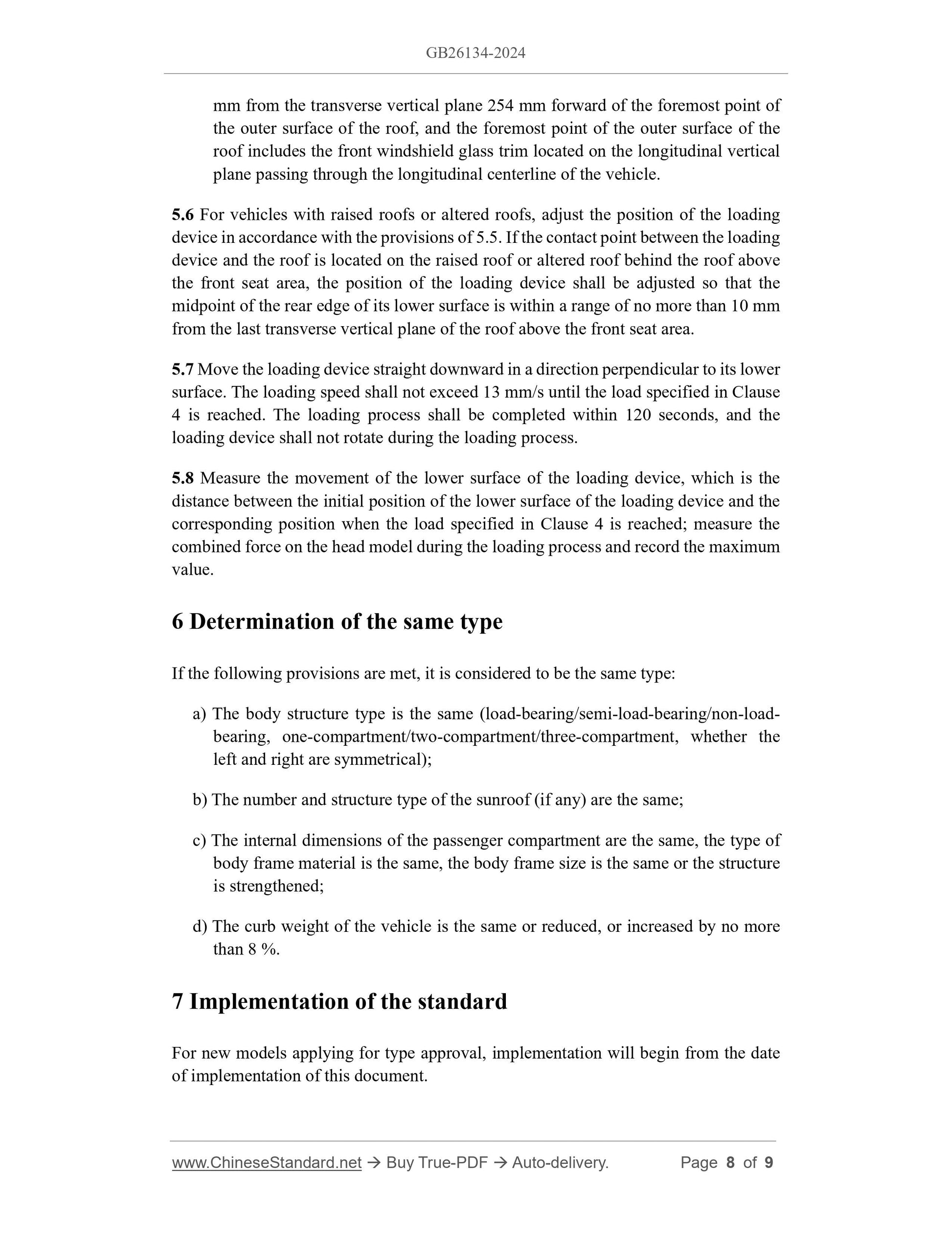
5.6 For vehicles with high roofs or replaceable roofs, adjust the position of the loading device in accordance with the provisions of 5.5.If the contact point between the loading device and the roof is
When the vehicle is located on a high roof or a replaceable roof behind the roof above the front seat area, the loading device should be positioned so that the center of the rear edge of the lower surface is
The point is located within a range of no more than 10 mm from the rearmost horizontal vertical plane of the roof above the front seat area.
5.7 Move the loading device in a straight line downward in a direction perpendicular to its lower surface. The loading speed shall not exceed 13 mm/s until the fourth
The loading process should be completed within 120 seconds, and the loading device should not rotate during the loading process.
5.8 Measure the displacement of the lower surface of the loading device, which is the displacement between the initial position of the lower surface of the loading device and the position where the loading is completed in accordance with the requirements of Chapter 4.
The distance between the corresponding positions when a certain load is applied; measure the resultant force on the head model during loading and record the maximum value.
6 Identical type determination
If the following requirements are met, they are considered to be of the same type.
a) The vehicle body structure is the same (load-bearing/semi-load-bearing/non-load-bearing, one-box/two-box/three-box, whether the left and right are symmetrical);
b) The number and structure of skylights (if any) are the same;
c) The internal dimensions of the passenger compartment are the same, the type of body frame material is the same, the body frame dimensions are the same or the structure is strengthened;
d) The vehicle's curb weight is the same or reduced, or increased by no more than 8%.
7 Implementation of the Standard
For new vehicle models applying for type approval, implementation shall begin from the date of implementation of this document.
For vehicle models that have obtained type approval, implementation will begin on the 25th month from the date of implementation of this document.

View full details