1
/
of
7
PayPal, credit cards. Download editable-PDF & invoice in 1 second!
GB 17510-2008 English PDF (GB17510-2008)
Regular price
$105.00 USD
Regular price
Sale price
$105.00 USD
Unit price
/
per
Shipping calculated at checkout.
Couldn't load pickup availability
Delivery: 3 seconds. Download true-PDF + Invoice.
Get Quotation: Click GB 17510-2008 (Self-service in 1-minute)
Historical versions (Master-website): GB 17510-2008
Preview True-PDF (Reload/Scroll-down if blank)
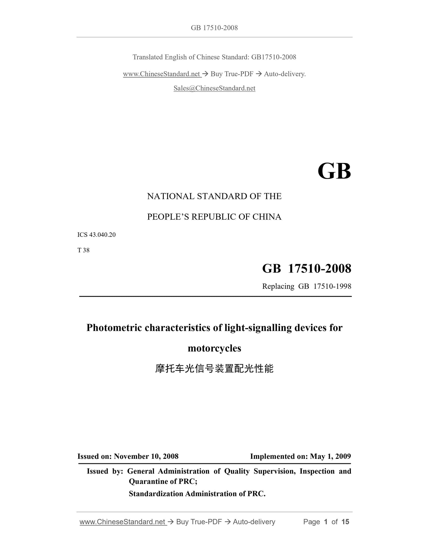
GB 17510-2008: Photometric characteristics of light-signalling devices for motorcycles
GB 17510-2008
Photometric characteristics of light-signalling devices for motorcycles
ICS 43.040.20
T38
National Standards of People's Republic of China
Replacing GB 17510-1998
Motorcycle light signaling devices for optical performance
Posted 2008-11-10
2009-05-01 implementation
Administration of Quality Supervision, Inspection and Quarantine of People's Republic of China
Standardization Administration of China released
Foreword
All the technical contents of this standard is mandatory.
This standard corresponds to United Nations Economic Commission for Europe ECER50-2004 "on mopeds and motorcycles front position lamps, rear position lamps,
Brake lights, turn lights and license plate lights certified Uniform provisions "non-equivalent, the main differences are as follows.
--- Remove the management provisions;
--- Remove the "minimum requirements for manufacturing consistency test" annex;
Size and measuring point --- license plates have been amended in accordance with China's national conditions.
The main technical requirements, such as. general technical requirements, light intensity, light color and test methods are consistent with the above regulations.
This standard replaces GB 17510-1998 "Motorcycle light signaling devices for optical performance," compared with the previous version of the main changes are as follows.
--- Revised version 3.2 and version 4.2 of the turn signal classification and limits;
--- Remove the previous version 3.3 Class 1 and Class 2 license plate sizes;
--- The maximum value for the previous version 4.2 brake lights;
--- Modify the previous version 5.1 front position lamp light color requirements;
--- Modify the previous version 9.1, different types of decision rules;
--- Increase the maximum limit mixed with headlight front position lamp;
--- Added a plurality of mounting positions luminaire testing requirements;
--- Increased non-filament bulb lights testing requirements;
--- Increased testing requirements lamps flicker work.
From the date of implementation of this standard, GB 17510-1998 abolished. The new application type inspection apparatus, shall comply with this standard.
Transitional requirements for implementation of this standard. a standard edition for prior examination carried out by the type of device, the corresponding provisions are subject to the control standard edition
Discrepancies, given the transitional period of 24 months.
This standard was proposed by the National Development and Reform Commission.
This standard by the National Automotive Standardization Technical Committee.
This standard was drafted. Shanghai Automotive Lamp Research Institute, the National Motorcycle Quality Supervision and Inspection Center (Tianjin).
The main drafters of this standard. Fei Yin, Yu Peifeng, Li Gang.
This standard replaces the standards previously issued as follows.
--- GB 17510-1998.
Motorcycle light signaling devices for optical performance
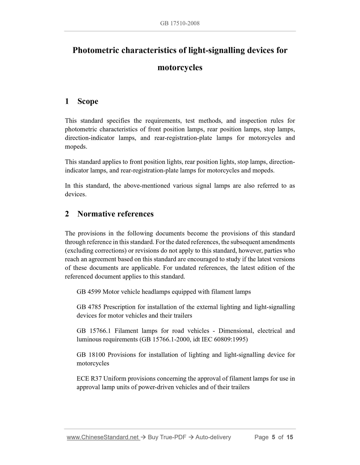
1 Scope
This standard specifies the motorcycles and mopeds front position lamps, rear position lamps, brake lights, turn lights and rear registration plate lamps for light distribution
Energy requirements, test methods and inspection rules.
This standard applies to motorcycles and mopeds front position lamps, rear position lamps, brake lights, turn lights and rear registration plate lamp.
In this standard, also known as the above signal means.
2 Normative references
The following documents contain provisions which, through reference in this standard and become the standard terms. For dated references, subsequent
Amendments (not including errata content) or revisions do not apply to this standard, however, encourage the parties to the agreement are based on research
Whether the latest versions of these documents. For undated reference documents, the latest versions apply to this standard.
GB 4599 automobile headlamp with filament lamps
GB 4785 Installation regulations for car and trailer exterior illumination and light signaling devices
GB 15766.1 Filament lamps for road vehicles - Dimensional, electrical and performance requirements (GB 15766.1-2000, idt IEC 60809.1995)
Installation instructions GB 18100 motorcycles lighting and light signaling devices
ECER37 Uniform provisions concerning the certification of motor vehicles and their trailers lamps with filament lamps certified
3 Terms and Definitions
Terms and definitions established in GB 18100 apply to this standard.
Category 4
4.1 Press on the vehicle the minimum angular extent of the installation location and function of a specified class means and light distribution.
The following Figures 1, 2, 3 and 4 vertical angle V angle with respect to the horizontal plane, above the level of positive, negative below the horizontal;
Horizontal angle H with respect to the reference axis and the direction of travel of the vehicle forward angle. In photometric state apparatus, in the reference axis of the right to
We are in the reference axis of the left negative. The arrows indicate the direction of travel of the vehicle forward.
4.1.1 Front position lamps divided (see Figure 1).
a) Individually installed front position lamp;
b) a pair of front position lamps installed.
V = + 15 ° ~ -10 °
Front position lamps a) separately installed
V = + 15 ° ~ -10 °
b) Front position lamps installed in pairs (right side)
Figure 1 Front position lamps Categories and light distribution minimum angle
4.1.2 The rear position lamps are divided into (see Figure 2).
a) rear position lamps installed separately;
b) Rear position lamps installed in pairs.
V = + 15 ° ~ -10 °
a) Individually installed rear position lamp
V = + 15 ° ~ -10 °
b) rear position lamps installed in pairs (right side)
Category 2 and rear position lamps light distribution minimum angle
4.1.3 turn signal is divided into (see Figure 3).
a) 11 class means and adjacent light near the minimum distance between two lamps not less than 75mm front turn signal;
b) 11a class means and adjacent light near the minimum distance between two lamps not less than 40mm front turn signal;
c) 11b class means and adjacent light near the minimum distance between two lamps not less than 20mm front turn signal;
d) 11c class device near dipped lights two lamps before the minimum spacing is less than 20mm turn signal;
e) 12 motorcycle class device mounted at the rear turn signals.
V = ± 15 °
11 categories, 11a class, 11b category, 11c and 12 class class turn signals
Figure 3 categories and turn signal light distribution minimum angle
4.1.4 brake light (see Figure 4).
V = + 15 ° ~ -10 °
Brake lights
Figure 4 brake lights light distribution minimum angle
5 different types of devices
In the following main aspects are different means.
a) trade names or trademarks;
B) the characteristics of the optical system (luminous intensity level, the type of light distribution minimum angle, using a filament lamp or light source module, etc.);
c) device class.
However, changing the color of the filament lamp or the color filter does not affect the type of change.
6 Requirements
6.1 General Requirements
6.1.1 The device shall be designed and manufactured under normal conditions of use, even when subjected to vibration, should meet the requirements and to ensure compliance with this standard
Provisions.
6.1.2 For the light source module shall be designed to be even in the dark can also install it in the correct position; and prevent
Misuse.
6.1.3 If filament bulbs, the bulbs should be in line with GB 15766.1 or ECER37 regulations.
6.2 light performance
6.2.1 front position lamps, rear position lamps, brake lights and turn signal light distribution requirements shown in Figure 5, the digital figure grid lines cross is the percentage
The ratio of the minimum number, it indicates that this standard requires the minimum luminous intensity and direction of the reference axis directional light intensity, the figure of H = 0 ° and
V = 0 ° corresponds to the reference axis direction.
(See Figure 5), in the light emitted by a variety of means should be uniform, that is in the range of grid lines enclosed in either direction measuring luminous intensity distribution
Too luminous intensity around the direction of not less than the minimum luminosity value in all directions.
Figure 5 luminous intensity distribution
6.2.2 The front position lamps, rear position lamps, brake lights and turn signals on the reference axis of the luminous intensity shall comply with the provisions in Table 1, and the light distribution
Luminous intensity within the angle range of not less than the minimum specified in Table 1. The minimum luminous intensity limit.
Table 1 front position lamps, rear position lamps, brake lights and turn signals on the reference axis of the unit of luminous intensity candela
Lamps Name Minimum Maximum Minimum angle light distribution within the range of the minimum luminous intensity limits
Rear position lamps 4 12a 0.05
Front position lamps 4 60b 0.05
Brake light 40 185 0.3
Table 1 (continued) in units of candela
Lamps Name Minimum Maximum Minimum angle light distribution within the range of the minimum luminous intensity limits
11 categories turn signal 90 700c 0.3
11a class turn signal 175 700c 0.3
Type 11b turn signal 250 800c 0.3
Class 11c turn signal 400 860c 0.3
12 class turn signal 50350 0.3
When the rear position lamp and a brake lamp when the composition of mixed light, allowing the lower level below 5 ° direction luminous intensity of 60cd.
b position lamp and headlamp are combined, a maximum of 100cd.
c The limit only applies within H = ± 5 ° and V = ± 10 ° range, outside H = ± 5 ° and V = ± 10 ° range of maximum light intensity limit of 400cd.
6.2.3 For more than a single light source lamp.
a) In any case a failure of the light source, should meet the minimum luminous intensity required value.
b) In the case of all light is lit, the maximum emission intensity by the maximum limit specified in Table 1 is multiplied by 1.4 to give.
c) All sources connected in series can be seen as a light source.
6.2.4 If the rear position lamp and brake lights or a combination of mixed into one device, then 11 in the measuring direction H = ± 10 ° and V = ± 5 ° range
The ratio of emission intensity (see Fig. 5), while the two lighted lamp is lit when a single rear position lamp and the actual measured to be less than 5.
If the rear position lamp and brake light that contains more than a single source of light, then the measurement values of all lights should be lit all measurements
inferred.
6.2.5 means the vehicle has more than one installation location, or within a region may have a plurality of different positions, it should be in all the bits
Repeated on the home photometric measurements; or by region relative to the limit positions specified by the manufacturer of the reference axis is measured.
6.2.6 the region of illumination, the illumination area and measuring points of the rear registration plate lamps as shown in Figure 6.
Millimeters
Measuring point illumination region and 6 rear registration plate lamps
6.2.7 rear registration plate lamp illumination brightness at each measurement point (see Figure 6) shall not be less than 2cd/m2, brightness uniformity and comply with the following requirements.
B2-B1
L ≤2B0 cm
Where.
B1 and B2 --- two arbitrary luminance measurement points, the unit is candela per square meter (cd/m2);
The minimum brightness of all measurement points B0 --- shown in FIG. 6, the unit is candela per square meter (cd/m2);
L --- B1 and B2 distance between centimeters (cm).
6.2.8 Manufacturers should provide a license plate lamp or more locations, and the license plate or a related area, the device is suitable for installation
Set; when the lamp is installed in the location specified by the manufacturer on the light emission angle of incidence for any point on the registration plate should not be illuminated
Chaoguo 82 °, this angle position measuring extreme distance from the surface of the license plate lighting the farthest regions; If the device contains one or more lighting
Optical unit, then this requirement shall apply only to the relevant part of the illumination provided by the relevant unit of the illumination area.
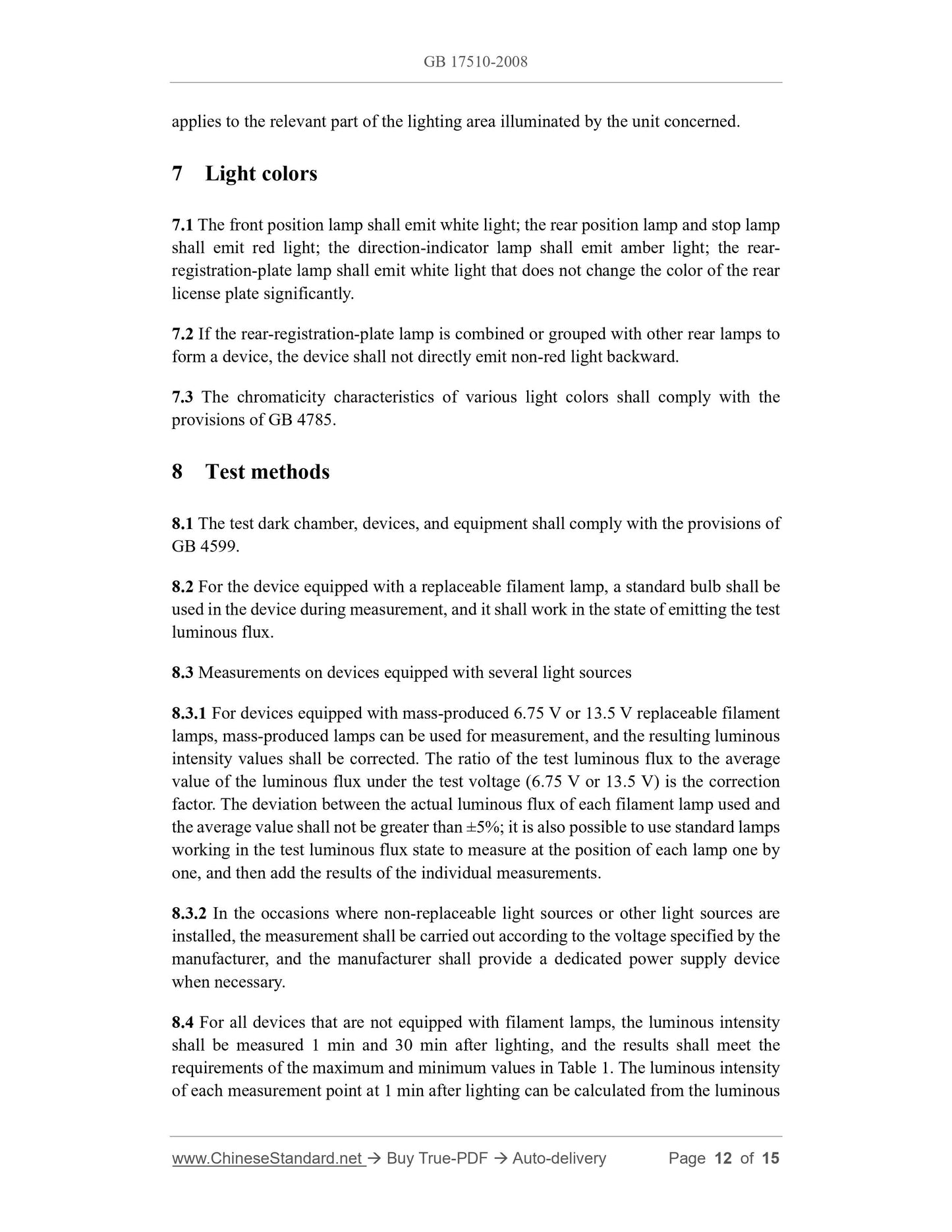
7 light color
7.1 front position lamp emitting white light; rear position lamps and stop lamps emit red light; turn indicators shall emit amber light; rear registration plate lamp shall not transmit
License plate after making significant changes in the color of white light.
7.2 If a rear registration plate lamp and other rear lamp or is combined into one device, the device shall not directly emit non-red light.
7.3 wide range of color characteristics of the light color should be consistent with the provisions of GB 4785.
8 Test methods
8.1 Test darkrooms, plant and equipment shall comply with the provisions of GB 4599.
8.2 pairs fitted with replaceable filament light bulbs, should be measured using a standard light bulb in the device and make it work in the test luminous flux emitted
status.
8.3 fitted with several light sources measuring device
8.3.1 fitted with mass production of 6.75V or 13.5V filament light bulbs, light bulbs can be used for mass production measurements, the
The luminous intensity values produced shall be corrected. Test luminous flux test voltage (6.75V or 13.5V) than the average value for the luminous flux under repair
Positive coefficient. The actual flux of each filament lamp used its average value should be less than ± 5%; and to be in each bulb
Position one by one using a standard bulb working in state experimental flux measurements and individual measurements in each position on the result of the addition.
8.3.2 fitted with non-interchangeable or other light sources of the occasion, according to the voltage measurements specified by the manufacturer, the manufacturer shall provide dedicated needed
Power supply unit.
8.4 For all not equipped with filament lamps means, after lighting 1min and 30min, respectively, should be measured luminous intensity, as a result
Table 1 should be consistent with the maximum and minimum requirements; at each measurement point in the luminous intensity 1min after lighting c...
Share