Skip to product information
1 of 12

PayPal, credit cards. Download editable-PDF and invoice in 1 second!

GA 1210-2014 English PDF (GA1210-2014)

GA 1210-2014 English PDF (GA1210-2014)

Regular price $150.00 USD
Regular price Sale price $150.00 USD
Sale Sold out
Shipping calculated at checkout.
Delivery: 3 seconds. Download true-PDF + Invoice.
Get Quotation: Click GA 1210-2014 (Self-service in 1-minute)
Historical versions (Master-website): GA 1210-2014
Preview True-PDF (Reload/Scroll-down if blank)

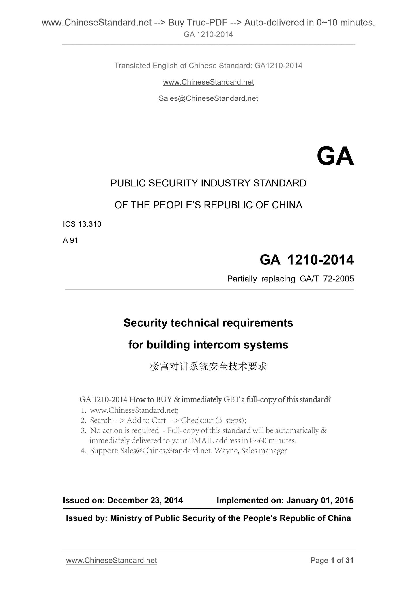
GA 1210-2014: Security technical requirements for building intercom systems
GA 1210-2014
Security technical requirements for building intercom systems
ICS 13.310
A91
People's Republic of China Public Security Industry Standard
Part of the replacement GA/T 72-2005
Building intercom system security technical requirements
2014-12-23 release
2015-01-01 implementation
Issued by the Ministry of Public Security of the People's Republic of China
Preface
The technical content of this standard is mandatory.
This standard is drafted in accordance with the rules given in GB/T 1.1-2009.
Please note that some of the contents of this document may involve patents. The issuer of this document does not assume responsibility for the identification of these patents.
This standard part of the replacement GA/T 72-2005 "floor intercom system and electronic control security door general technical conditions."
This standard is proposed by the National Security and Alarm System Standardization Technical Committee (SAC/TC100).
The third institute of the Ministry of Public Security, the Ministry of Public Security, the first Institute, the national security alarm system product quality supervision and inspection
(Shanghai), the National Security and Alarm System Product Quality Supervision and Inspection Center (Beijing), China Security Technology Prevention and Certification Center, Xiamen
Door legislature Lin Technology Co., Ltd., Shenzhen as Anluo Long Electronics Co., Ltd., Fujian Guanlin Technology Co., Ltd., Xiamen Di Nike
Electronic Technology Co., Ltd., Zhongshan City Austrian Min Electronics Co., Ltd.
The main drafters of this standard. Rong Ling, Liu Jianfeng, Sun Yuli, Shi Yuan, Zhang Jianguo, Jin Wei, Tang Guangyao, Zhang Dayong, Chen Mi, Chen Ping, Duan Yajun.
As of the date of implementation, GA/T 72-2005 shall be repealed.
The previous version of this standard is released.
- GA/T 72-1994, GA/T 72-2005.
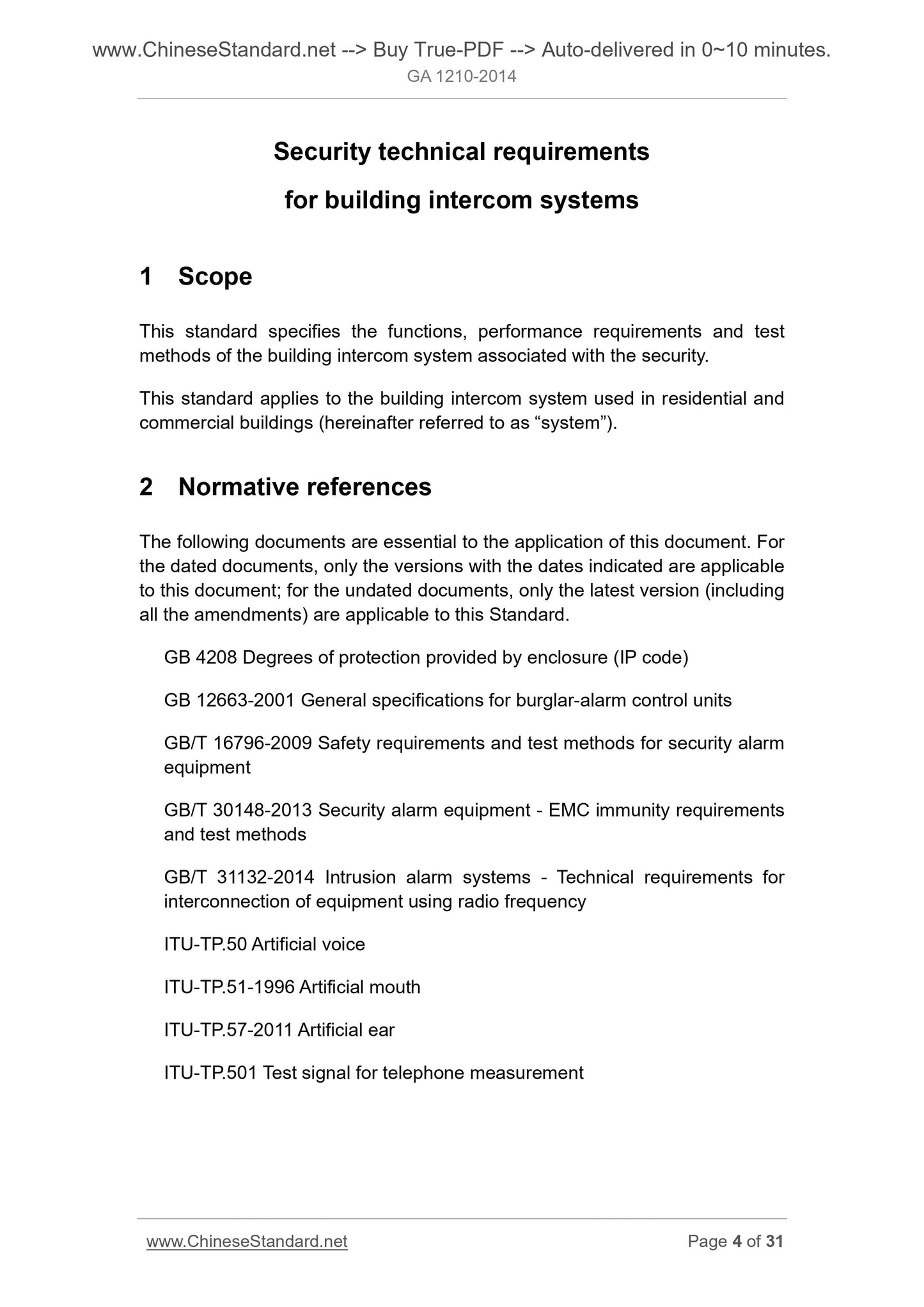
Building intercom system security technical requirements
1 Scope
This standard specifies the functions, performance requirements and test methods associated with the safety of the building intercom system.
This standard applies to residential and commercial buildings used in the building intercom system (hereinafter referred to as "system").
2 normative reference documents
The following documents are indispensable for the application of this document. For dated references, only the dated edition applies to this article
Pieces. For undated references, the latest edition (including all modifications) applies to this document.
GB 4208 enclosure protection class (IP code)
General technical requirements for burglar alarm controllers GB 12663-2001
Safety precautions - Safety equipment - Safety requirements and test methods GB/T
GB/T 30148-2013 Safety and alarm equipment - Electromagnetic compatibility immunity requirements and test methods
GB/T 31132-2014 intrusion alarm system wireless (radio frequency) interconnection equipment technical requirements
ITU-TP.50 emulation voice
ITU-TP.51-1996 simulation mouth
ITU-TP.57-2011 artificial ear
ITU-TP.501 Test signal for telephone measurement
3 terms, definitions and abbreviations
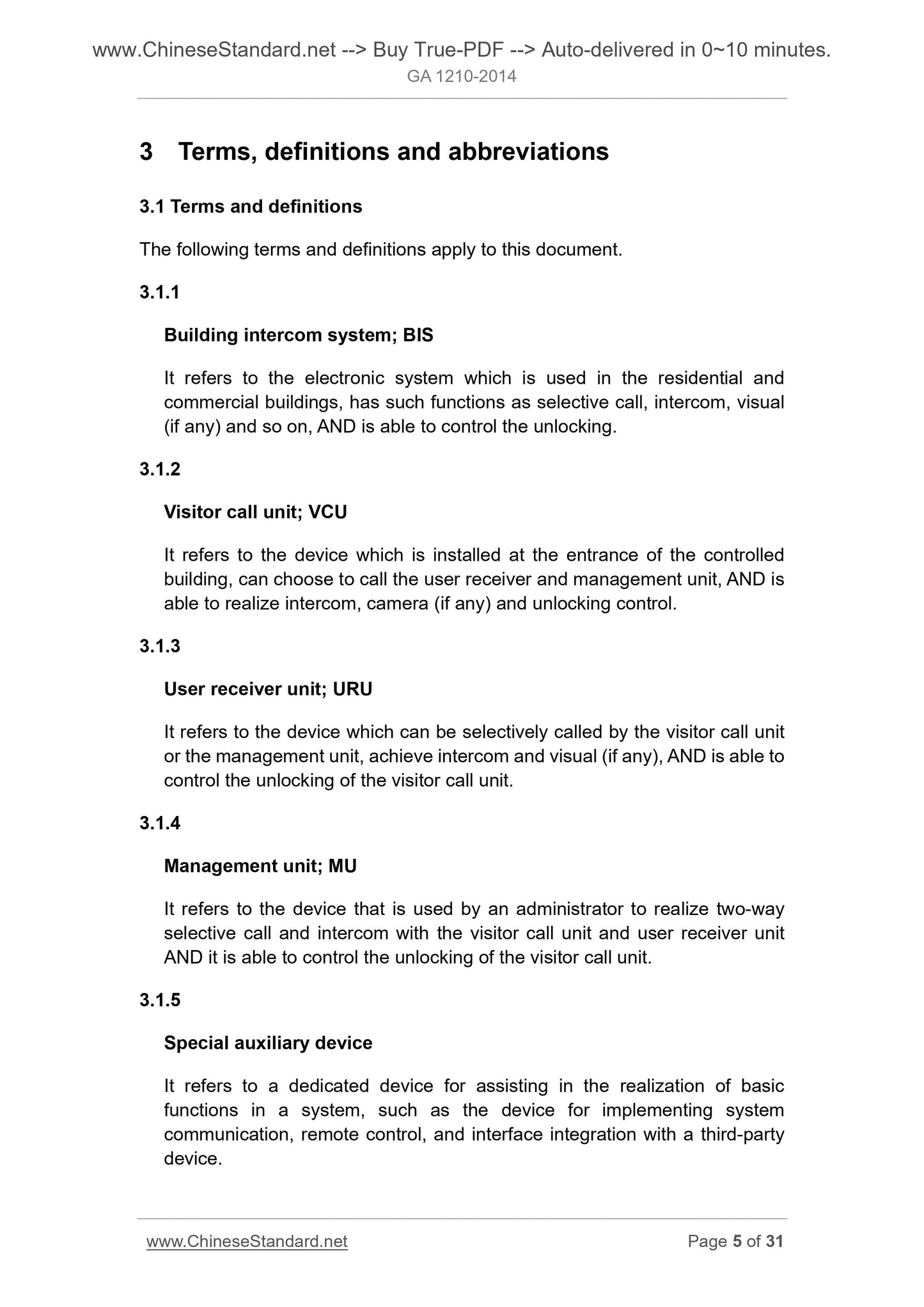
3.1 Terms and definitions
The following terms and definitions apply to this document.
3.1.1
Building intercom system buildingintercomsystem; BIS
For residential and commercial buildings, with selective call, intercom, visual (if any) and other functions, and can control the unlock of the electronic system.
3.1.2
Visitor call machine visitorcalunit; VCU
Installed at the entrance of the controlled building, can choose to call the user receiver and management machine, and can achieve intercom, camera (if any) and control unlock
Device.
3.1.3
User Receiver userreceiverunit; URU
Can be called by the customer call machine or management machine call, to achieve intercom, visual (if any), and can control the guest call machine unlock device.
3.1.4
Management machine managementman;
One for the administrator to use, with the guest call machine, the user receiver two-way selective call, speaking, and can control the guest call machine unlock
Device.
3.1.5
Special auxiliary equipment specialauxiliarydevice
A dedicated device for assisting in the realization of basic functions, such as for the transmission of a system, remote control, and a third party device
Interface integration and other functions of the device.
3.1.6
Common auxiliary device commonauxiliarydevice
A common device used in the system to assist in the realization of basic functions.
3.1.7
Simulation mouth artificialmouth
An analog sound device complying with the requirements of Chapter 5 of ITU-T Rec.
3.1.8
Imitation ear artificialear
A device that complies with Type 1 requirements in ITU-TP.57-2011.
3.1.9
Ear reference point
Located at the center of the artificial ear entrance plane, traditionally used to calculate the loudness rating point.
3.1.10
Mouth reference point mouthreferencepoint; MRP
Located on the reference axis, 25mm away from the front of the lip plane.
3.1.11
Full loudness assessment
The measure of the loudness of the channel between the sending end reference point and the receiving end reference point, in dB.
3.1.12
Full - range sensitivity/frequency characteristics overalsensitivity/frequencycharacteristics
The gain of the sound pressure of the receiving end reference point relative to the excitation pressure of the reference point of the transmitting port, in dB, is a function of frequency.
3.1.13
Audio delay acousticdelay
The voice signal is input by the transmit port reference point, and the desired one-way delay time is output through the system components to the receiving ear reference point.
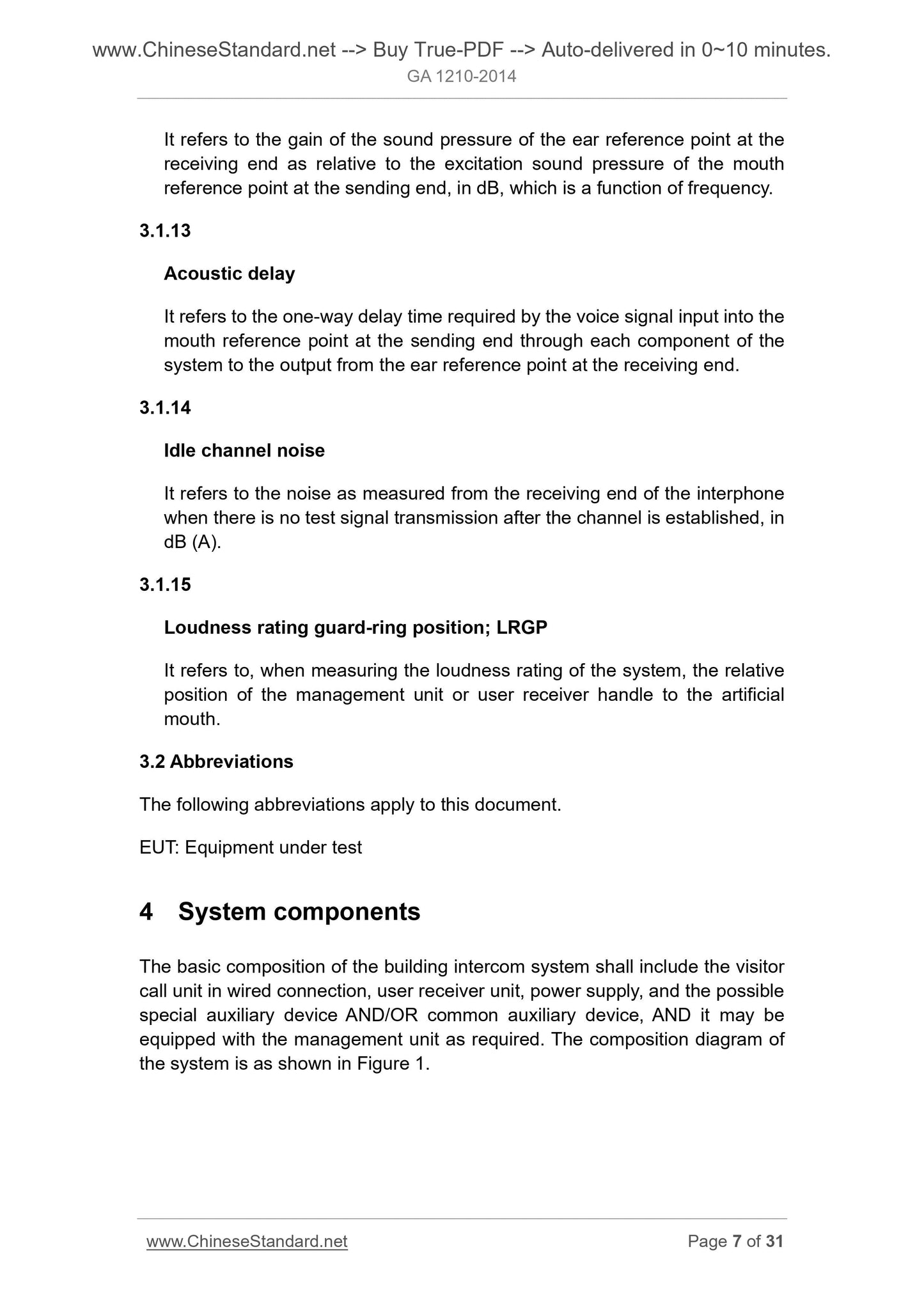
3.1.14
Idle channel noise idlechannelnoise
After the channel is established, the noise measured in the talk receiver when no test signal is transmitted is in dB (A).
3.1.15
Loudness Rating Protection Ring Location loudnessratingguard-ringposition; LRGP
When measuring the loudness rating of the system, the relative position of the manager or user receiver handle and emulation nozzle.
3.2 abbreviations
The following abbreviations apply to this document.
EUT. EquipmentUnderTest
4 system components
The basic composition of the building intercom system should include a wired connection to a guest caller, a user receiver, a power supply and a special auxiliary equipment that may be required
And/or universal accessory, which can be configured according to management needs. The composition of the system diagram shown in Figure 1.
Note 1.n is the number of guest calls, m is the number of user receivers, k is the number of management machines.
Note 2. The dotted line is an optional part.
Figure 1 Schematic diagram of the composition of the system
5 functional requirements
5.1 Basic functional requirements
5.1.1 Calling
The guest caller should be able to call the user receiver. During the call, the guest caller should have an audible and/or visual prompt;
Received a call signal should be issued after the hearing prompt.
5.1.2 Talkback
The system should have a two-way call function, speaking voice should be clear, continuous and no obvious missing syllable phenomenon, the system should have a limit call
Long function.
5.1.3 Visualization
A user receiver with a visual function should be able to display the image taken by the guest caller.
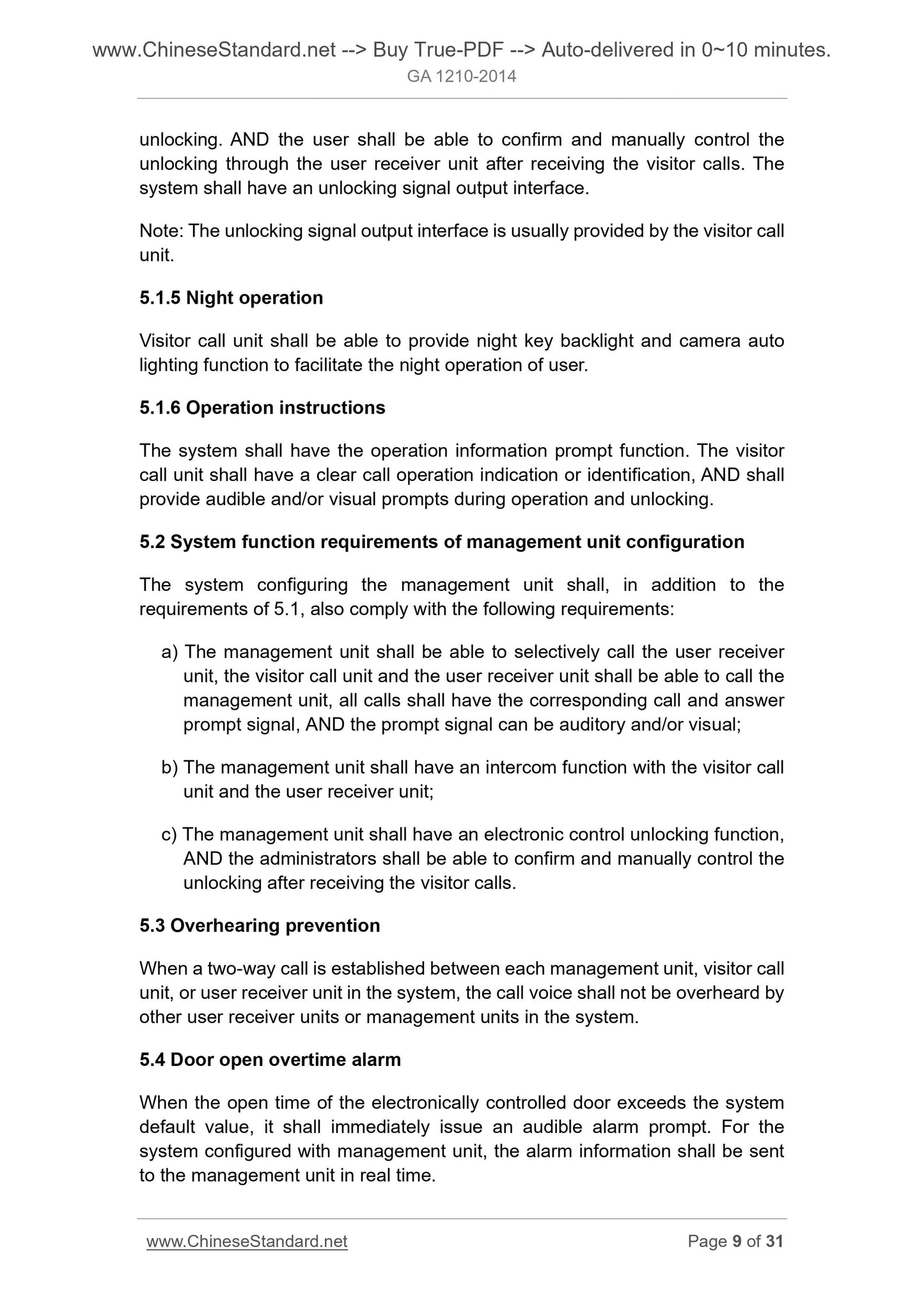
5.1.4 unlocking
The system should have the function of electrically connecting to the guest call machine through the wired connection of the user receiver, and the user should be able to call the guest,
Confirmation by user receiver and manual control of unlocking. The system should have an unlocked signal output interface.
Note. The unlocked signal output interface is usually provided by the guest caller.
5.1.5 Night operation
Visitor call machine should be able to provide night key backlight, camera auto fill light function, user-friendly night operation.
5.1.6 Operation instructions
The system should have the prompt function of the operation information. The guest caller should have a clear call operation indication or logo, during operation and on
The lock should be able to provide audible and/or visual hints.
5.2 Configure the system function requirements of the management machine
The system of the configuration manager should include the following requirements in addition to the requirements of 5.1.
a) The manager should be able to call the user receiver, the guest caller and the user receiver should be able to call the manager, all calls should have a corresponding
Call and answer prompt signals, the prompt signal can be auditory and/or visual;
b) the management machine should have a function with the guest call machine, the user receiver intercom;
c) The management machine should have an electronic control unlock function, and the manager should be able to confirm and manually control the lock after the visitor calls.
5.3 anti-string listen
When a two-way call is established between each administrator, guest caller, or user receiver in the system, the call voice should not be used by the system
Household receiver or management machine.
5.4 door open alarm
When the electronic control unlocking door opening time exceeds the system default value, should immediately issue an audible alarm prompt. For configuration management
Machine system, alarm information should be sent to the management machine in real time.
5.5 tampering
When the guest call machine is moved away from the mounting surface, a local audible alert prompt should be issued immediately. For the configuration of the management system, the alarm
The information should be sent to the management machine in real time.
5.6 Alarm Control Management
With the alarm control and management functions of the system, alarm control management functions should be consistent with the requirements of Appendix A.
5.7 wireless extension terminal
According to user needs, the user receiver can be an external wireless expansion terminal. The wireless extension terminal may have an alarm receiving function, but should not have
Alarm control management functions and electronic control unlock function.
6 performance requirements
6.1 Audio features
6.1.1 Full Loudness Rating (OLR)
The full range of loudness ratings in the range of.200 Hz to 4000 Hz shall meet the following requirements.
a) guest caller end .20 10-5 dB;
b) User receiver with hands-free calling, management terminal .23 10-5 dB;
c) The user receiver using the handle mode, management machine side .15dB ± 5dB.
6.1.2 Full sensitivity/frequency characteristics
Typical curves and tolerances in the range of 500 Hz to 3400 Hz should meet the following requirements.
a) Guest call machine, user receiver or management machine with handsfree mode. Typical curve is dotted line in Figure 2, tolerance range
As shown in Figure 2;
Figure 2 Full Sensitivity/Frequency Characteristics Template - Handsfree
b) the user receiver or manager terminal with the handle mode. The typical curve is the dotted line in Figure 3, the tolerance range is shown in Fig. 3
solid line.
Figure 3 Full Sensitivity/Frequency Characteristics Template - Handle End
6.1.3 Audio delay
The audio delay of the system end-to-end should not be greater than 300ms.
6.1.4 Idle channel noise
The idle signal noise should meet the following requirements.
a) Guest caller side, user receiver or management machine with handsfree mode should not be greater than 45dB (A);
b) A user receiver or management machine with a handle call should not be greater than 48 dB (A).
6.1.5 Ringing sound pressure
The ringing sound pressure should be not less than 73dB (A) and not more than 106dB (A).
6.2 Video Features
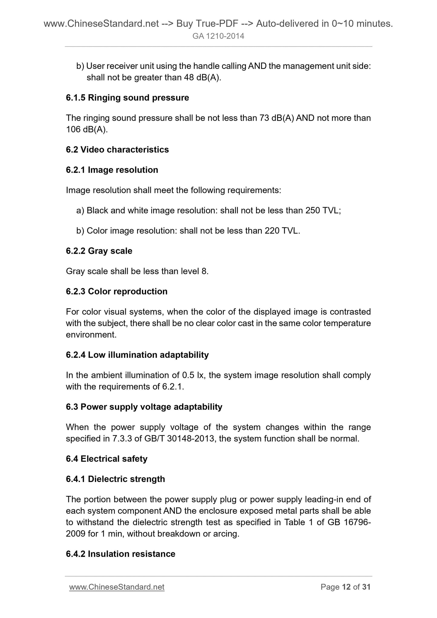
6.2.1 image resolution
Image resolution should meet the following requirements.
a) black and white image resolution should be less than 250TVL;
b) color image resolution should not be less than 220TVL.
6.2.2 Grayscale
Grayscale should be less than 8 levels.
6.2.3 color reproduction
For color visual systems, the color of the displayed image is contrasted with the subject, and there should be no clear color in the same color temperature environment.
6.2.4 Low Illumination Adaptability
In the ambient illumination 0.5lx, the system image resolution should meet the requirements of 6.2.1.
6.3 Power supply voltage adaptability
When the system power supply voltage changes within the range specified in 7.3.3 of GB/T 30148-2013, the system function should be normal.
6.4 Electrical safety
6.4.1 Dielectric strength
The system of the various components of the power plug or power supply and the exposed parts of the exposed metal parts should be able to withstand GB 16796-2009
Table 1 specified the electrical strength test, which lasted 1min should be no breakdown and arcing phenomenon.
6.4.2 Insulation resistance
The insulation resistance between the power plug of the components of the system or the exposed parts of the power supply and the exposed metal parts of the enclosure shall be
Not less than 5MΩ.
6.4.3 Leakage current
AC power supply system components of the system, the leakage current should not be greater than 5mA (AC, peak).
6.4.4 Protection under fault conditions
In the event of failure to cause damage to the system, the system components should not cause combustion, nor should the equipment internal circuit damage
Bad. The system should ensure the safety of the user but allow the loss of some functions. Any failure of the user receiver should not affect other users to receive
Machine work.
6.5 Electromagnetic immunity requirements
The system shall be capable of withstanding the following electromagnetic interference as specified in GB/T 30148-2013.
a) power supply voltage sags and short interruptions;
b) electrostatic discharge immunity;
c) radio frequency electromagnetic radiation immunity;
d) Disturbance of conducted disturbances induced by radio frequency field;
e) electrical fast transient burst immunity;
f) surge (impact) immunity.
6.6 mark
System equipment should have a clear, permanent logo. The logo should include at least the following.
--- manufacturer's name;
--- product na...
View full details