Skip to product information
1 of 12

www.ChineseStandard.us -- Field Test Asia Pte. Ltd.

GB/T 24925-2019 English PDF (GB/T24925-2019)

GB/T 24925-2019 English PDF (GB/T24925-2019)

Regular price $385.00
Regular price Sale price $385.00
Sale Sold out
Shipping calculated at checkout.
GB/T 24925-2019: Low temperature valve - Technical specifications
Delivery: 9 seconds. Download (& Email) true-PDF + Invoice.
Get Quotation: Click GB/T 24925-2019 (Self-service in 1-minute)
Historical versions (Master-website): GB/T 24925-2019
Preview True-PDF (Reload/Scroll-down if blank)

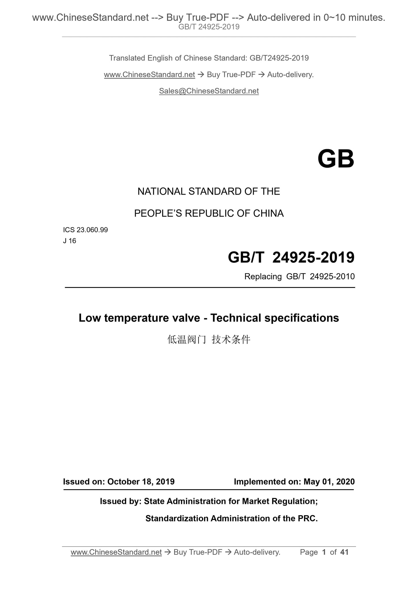
GB/T 24925-2019
NATIONAL STANDARD OF THE
PEOPLE’S REPUBLIC OF CHINA
ICS 23.060.99
J 16
Replacing GB/T 24925-2010
Low temperature valve - Technical specifications
ISSUED ON: OCTOBER 18, 2019
IMPLEMENTED ON: MAY 01, 2020
Issued by: State Administration for Market Regulation;
Standardization Administration of the PRC.
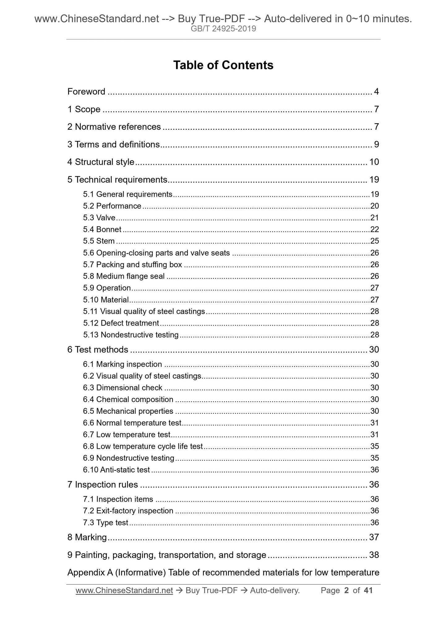
Table of Contents
Foreword ... 4 
1 Scope ... 7 
2 Normative references ... 7 
3 Terms and definitions ... 9 
4 Structural style ... 10 
5 Technical requirements ... 19 
5.1 General requirements ... 19 
5.2 Performance ... 20 
5.3 Valve ... 21 
5.4 Bonnet ... 22 
5.5 Stem ... 25 
5.6 Opening-closing parts and valve seats ... 26 
5.7 Packing and stuffing box ... 26 
5.8 Medium flange seal ... 26 
5.9 Operation ... 27 
5.10 Material ... 27 
5.11 Visual quality of steel castings ... 28 
5.12 Defect treatment ... 28 
5.13 Nondestructive testing ... 28 
6 Test methods ... 30 
6.1 Marking inspection ... 30 
6.2 Visual quality of steel castings ... 30 
6.3 Dimensional check ... 30 
6.4 Chemical composition ... 30 
6.5 Mechanical properties ... 30 
6.6 Normal temperature test ... 31 
6.7 Low temperature test ... 31 
6.8 Low temperature cycle life test ... 35 
6.9 Nondestructive testing ... 35 
6.10 Anti-static test ... 36 
7 Inspection rules ... 36 
7.1 Inspection items ... 36 
7.2 Exit-factory inspection ... 36 
7.3 Type test ... 36 
8 Marking ... 37 
9 Painting, packaging, transportation, and storage ... 38 
Appendix A (Informative) Table of recommended materials for low temperature
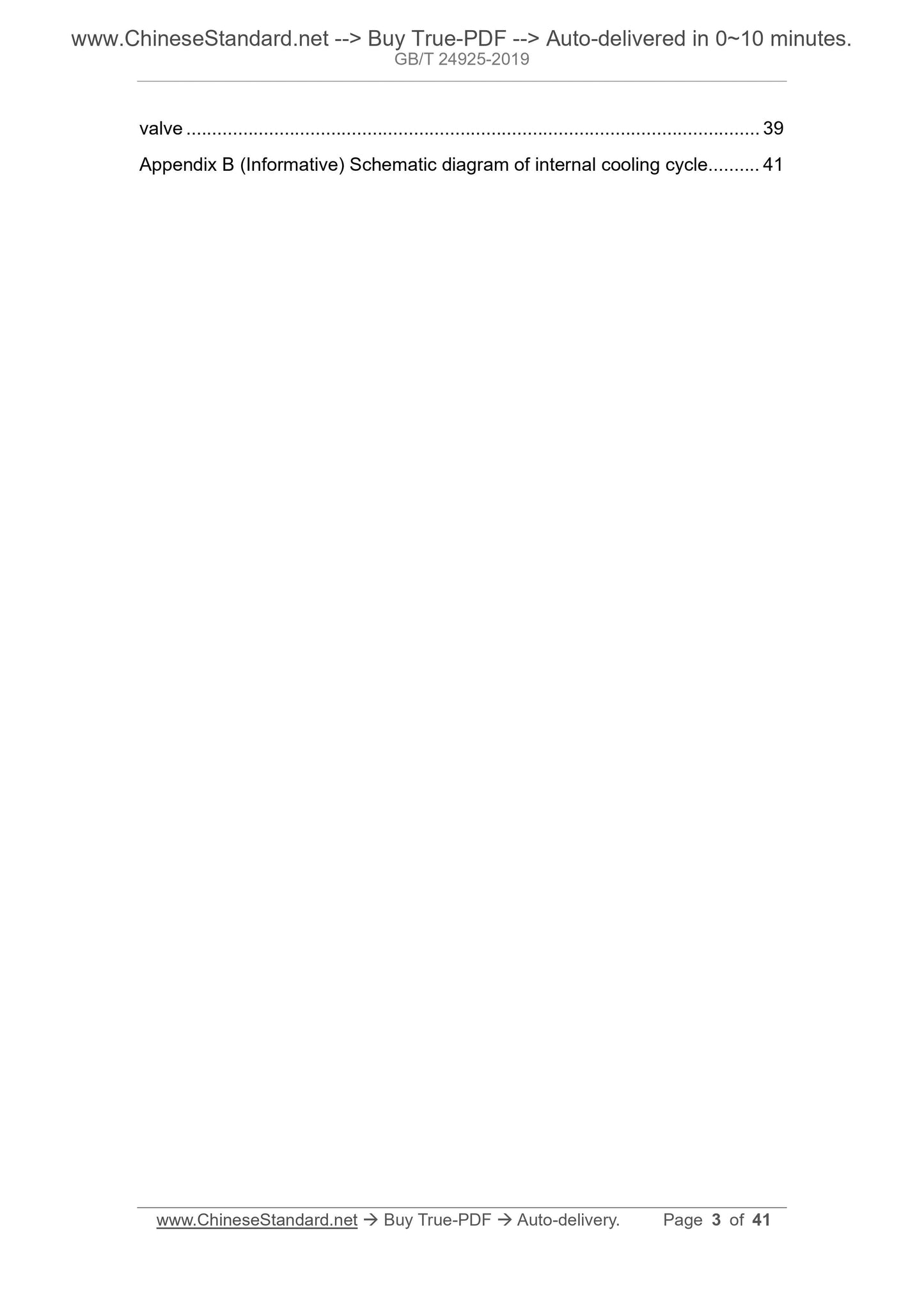
valve ... 39 
Appendix B (Informative) Schematic diagram of internal cooling cycle ... 41 
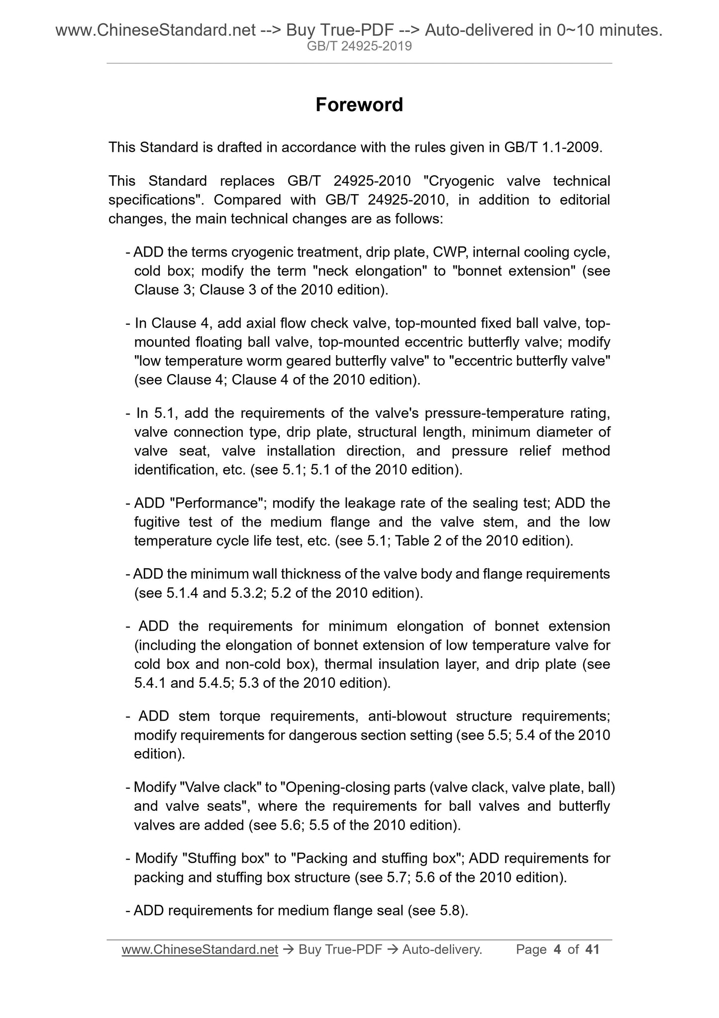
Foreword
This Standard is drafted in accordance with the rules given in GB/T 1.1-2009.
This Standard replaces GB/T 24925-2010 "Cryogenic valve technical
specifications". Compared with GB/T 24925-2010, in addition to editorial
changes, the main technical changes are as follows:
- ADD the terms cryogenic treatment, drip plate, CWP, internal cooling cycle,
cold box; modify the term "neck elongation" to "bonnet extension" (see
Clause 3; Clause 3 of the 2010 edition).
- In Clause 4, add axial flow check valve, top-mounted fixed ball valve, top-
mounted floating ball valve, top-mounted eccentric butterfly valve; modify
"low temperature worm geared butterfly valve" to "eccentric butterfly valve"
(see Clause 4; Clause 4 of the 2010 edition).
- In 5.1, add the requirements of the valve's pressure-temperature rating,
valve connection type, drip plate, structural length, minimum diameter of
valve seat, valve installation direction, and pressure relief method
identification, etc. (see 5.1; 5.1 of the 2010 edition).
- ADD "Performance"; modify the leakage rate of the sealing test; ADD the
fugitive test of the medium flange and the valve stem, and the low
temperature cycle life test, etc. (see 5.1; Table 2 of the 2010 edition).
- ADD the minimum wall thickness of the valve body and flange requirements
(see 5.1.4 and 5.3.2; 5.2 of the 2010 edition).
- ADD the requirements for minimum elongation of bonnet extension
(including the elongation of bonnet extension of low temperature valve for
cold box and non-cold box), thermal insulation layer, and drip plate (see
5.4.1 and 5.4.5; 5.3 of the 2010 edition).
- ADD stem torque requirements, anti-blowout structure requirements;
modify requirements for dangerous section setting (see 5.5; 5.4 of the 2010
edition).
- Modify "Valve clack" to "Opening-closing parts (valve clack, valve plate, ball)
and valve seats", where the requirements for ball valves and butterfly
valves are added (see 5.6; 5.5 of the 2010 edition).
- Modify "Stuffing box" to "Packing and stuffing box"; ADD requirements for
packing and stuffing box structure (see 5.7; 5.6 of the 2010 edition).
- ADD requirements for medium flange seal (see 5.8).
Low temperature valve - Technical specifications
1 Scope
This Standard specifies the structural style, technical requirements, test
methods, inspection rules, marking, painting, packaging, transportation, and
storage of low temperature valve (hereinafter referred to as "valve").
This Standard is applicable to flange, wafer and welding-connected low
temperature gate valves, globe valves, check valves, ball valves, and butterfly
valves with nominal pressure PN16~PN400, nominal size DN15~DN1200;
pressure class Class150~Class2500, nominal size NPS1/2~NPS48, medium
temperature -196 °C~-29 °C.
Other low temperature valves may refer to it for use.
2 Normative references
The following documents are indispensable for the application of this document.
For the dated references, only the editions with the dates indicated are
applicable to this document. For the undated references, the latest edition
(including all the amendments) are applicable to this document.
GB/T 229 Metallic Materials - Charpy Pendulum Impact Test Method
GB/T 9113 Integral steel pipe flanges
GB/T 12220 Industrial valves - Marking
GB/T 12221 Metal valves - Face to face, end to end, center to face and
center to end dimensions
GB/T 12222 Multi-turn valve actuator attachments
GB/T 12223 Part-turn valve actuator attachments
GB/T 12224 General requirements for industrial steel valves
GB/T 12225 General purpose industrial valves - Specification of copper alloy
castings
GB/T 12234 Bolted bonnet steel gate valves for petroleum and natural gas
industries
JB/T 8527 Metallic sealing butterfly valve
JB/T 12003 Specification for valve cryogenic test rig
JB/T 12622 Liquified natural gas valves - Performance testing
NB/T 47009 Alloy steel forgings for low temperature pressure equipment
NB/T 47010 Stainless and heat-resisting steel forgings for pressure
equipment
NB/T 47013.2-2015 Nondestructive testing of pressure equipment - Part 2:
Radiographic testing
NB/T 47013.4 Nondestructive testing of pressure equipment - Part 4:
Magnetic particle testing
NB/T 47013.5-2015 Nondestructive testing of pressure equipment - Part 5:
Penetrant testing
NB/T 47014 Welding procedure qualification for pressure equipment
3 Terms and definitions
The following terms and definitions apply to this document.
3.1
Bonnet extension
The part from the uppermost end of the bonnet support to the bottom of the
bonnet stuffing box.
The part from the top of lower bushing to the bottom of stuffing box of the bonnet
of the lift stem valve.
The part from the top of the lower bonnet bearing of the quarter-turn valve to
the bottom of the stuffing box.
3.2
Cryogenic treatment
The treatment process in which the parts are immersed in liquid nitrogen for
cooling, and when the temperature of the parts is stable at -196 °C, the heat is
kept for 2 h~4 h according to the thickness of the parts, and then taken out of
the box to naturally return to room temperature.
5 Technical requirements
5.1 General requirements
5.1.1 In addition to meeting the requirements of this Standard, the valve shall
also comply with the corresponding valve product standards, such as GB/T
12234, GB/T 12235, GB/T 12236, GB/T 12237, GB/T 21387, JB/T 8527, JB/T
7746.
5.1.2 The pressure-temperature rating of the valve shall comply with the
provisions of GB/T 12224 and JB/T 7746.
5.1.3 According to the contract requirements, the valve shall be provided with a
drip plate.
5.1.4 The end connection of the valve can be flanged or welded. The flange
shall comply with the provisions of GB/T 9113 and GB/T 13402. The welded
connection shall comply with the provisions of GB/T 12224, or as required by
the order contract. The structural length of the flange connection and welded
connection valve shall comply with the provisions of GB/T 12221, or as
specified in the order contract.
5.1.5 The structural length of the welded end valve shall consider the effect of
end welding on the seat seal. When the contract stipulates that a sleeve is
added to the welded end, the inside and outside diameter dimensions and
materials of the sleeve shall be consistent with or match the pipeline.
5.1.6 The valve and bonnet shall be connected by bolts, welding, or pipe joints.
The bonnet connected by pipe joints is only suitable for low temperature valves
with a nominal size not greater than DN50. The pipe joint nut shall be locked
with the valve. The threaded bonnet shall not be used.
5.1.7 The minimum diameter of the valve seat shall meet the requirements of
GB/T 12224, GB/T 28776, GB/T 12238 and related product standards, or
according to the order contract. The minimum diameter of the valve seat of
reduced-opening valve shall be in accordance with the order contract.
5.1.8 For the valve for transmitting liquid medium and the valve for non-cold
box, it shall be able to operate the valve stem on the ground at a direction not
less than 45° from the ground; see Figure 11 a). For the valve for cold box, it
shall be able to operate the valve stem on the ground at the direction of 15°~90°
from the ground; see Figure 11 b).
5.6 Opening-closing parts and valve seats
5.6.1 The sealing pair of low temperature valve shall be designed as a metal-
to-metal or metal-to-non-metal sealing surface.
5.6.2 The valve clack of globe valve shall adopt a conical or spherical sealing
structure. It shall not use flat-sealed valve clack.
5.6.3 The sealing pair of ball valve should adopt the elastic element loading
structure, to meet the one-way sealing requirements.
5.6.4 The sealing pair of butterfly valve shall adopt double-eccentric or triple-
eccentric structure. It shall meet the requirements of one-way sealing. When
required by the order contract, it shall also meet the requirements of two-way
sealing.
5.6.5 The overlaying-welding hard alloy on the sealing surface of the closing
part and the valve seat shall comply with the provisions of JB/T 6438 or relevant
standards. The thickness of the overlaying-welding layer after processing shall
not be less than 1.6 mm. When the use temperature is lower than -100 °C, after
overlaying welding, cryogenic treatment shall be carried out.
5.7 Packing and stuffing box
5.7.1 The packing shall meet the performance requirements of small friction
coefficient and good wear resistance; under the conditions of use, have good
material toughness and ductility.
5.7.2 According to the use temperature, the packing can adopt multiple
combinations of PTFE, flexible graphite, and lip seal ring, or according to the
requirements of the order contract.
5.7.3 The surface roughness Ra value of stuffing box shall be no more than 1.6
μm.
5.7.4 The packing pressing device shall not, in the form of threaded connection
with the bonnet, apply a pre-tightening force to the packing.
5.7.5 When required in the order contract, bellows can be used for sealing at
the valve stem.
5.7.6 When required in the order contract, the structural design of the stuffing
box shall meet the fugitiveness requirements.
5.8 Medium flange seal
The medium flange seal should adopt metal wound flexible graphite gaskets
and metal ring gaskets with resistance to temperature alternation and high
5.13.1.1 The pressure castings shall be subjected to radiographic testing. The
testing locations are as follows:
a) For casting shells, according to the parts specified in GB/T 12224;
b) Butt welding seam and welding groove.
5.13.1.2 The inspection results shall meet the following requirements:
a) The radiographic testing of the steel castings of valve and bonnet is not
lower than the requirements of level 2 in JB/T 6440-2008;
b) The radiographic testing of the connection end of the valve at the butt
welded joint meets the requirements of level 1 in JB/T 6440-2008;
c) The radiographic testing of the pressure welds is not lower than the
requirements of class I in NB/T 47013.2-2015.
5.13.2 Liquid penetrant testing
The pressure-bearing outer surface of the valve and bonnet, the accessible
inner surface, and the overlaying-welding surface of hard alloy sealing surface
shall be subjected to liquid penetrant testing. The overlaying-welding surface of
hard alloy sealing surface shall not have any harmful defects. The testing of the
overlaying-welding surface shall be carried out in accordance with the
provisions of GB/T 22652. Other testing results shall meet the following
requirements:
a) No crack;
b) The maximum allowable length of linear and non-linear defects meets the
requirements of level 2 in NB/T 47013.5-2015.
5.13.3 Ultrasonic testing
Forged valve body, bonnet, and stem, etc. shall be subjected to ultrasonic
testing. The inspection result shall not be lower than the requirements of level
2 in JB/T 6903-2008.
5.13.4 Magnetic particle testing
5.13.4.1 The parts and locations tested by magnetic particle are the pressure-
bearing outer surfaces of the valve body and bonnet of ferromagnetic material.
5.13.4.2 The defect at the welding groove location shall not be lower than the
requirements of level 1 in JB/T 6439-2008. Defects at other locations shall not
be lower than the requirements of level 2 (including level 2). There shall be no
cracks and linear defects in the magnetic particle inspection locations.
in the valve body, there shall be temperature thermocouple in the cooling
medium. If the nominal size of the test valve is small, only one thermocouple
may be placed in the flange part of the valve body and the inside of the valve
body, respectively.
6.7.2.5 Test preparation
Before the test, the valve parts shall be degreased and dried. The valve shall
be installed in a clean and dustproof environment. Except for the primer, the
valve shall not be painted.
6.7.3 Test procedure
6.7.3.1 The normal temperature test uses nitrogen or air as the initial detection
test, to ensure that the valve is tested under appropriate conditions.
6.7.3.2 The typical test device of low temperature valve is shown in Figure 13.
Install the valve in the test container; connect all the joints, to...
View full details