1
/
of
12
www.ChineseStandard.us -- Field Test Asia Pte. Ltd.
GB/T 18204.1-2013 English PDF (GB/T18204.1-2013)
GB/T 18204.1-2013 English PDF (GB/T18204.1-2013)
Regular price
$205.00
Regular price
Sale price
$205.00
Unit price
/
per
Shipping calculated at checkout.
Couldn't load pickup availability
GB/T 18204.1-2013: Examination methods for public places - Part 1: Physical parameters
Delivery: 9 seconds. Download (& Email) true-PDF + Invoice.
Get Quotation: Click GB/T 18204.1-2013 (Self-service in 1-minute)
Historical versions (Master-website): GB/T 18204.1-2013
Preview True-PDF (Reload/Scroll-down if blank)
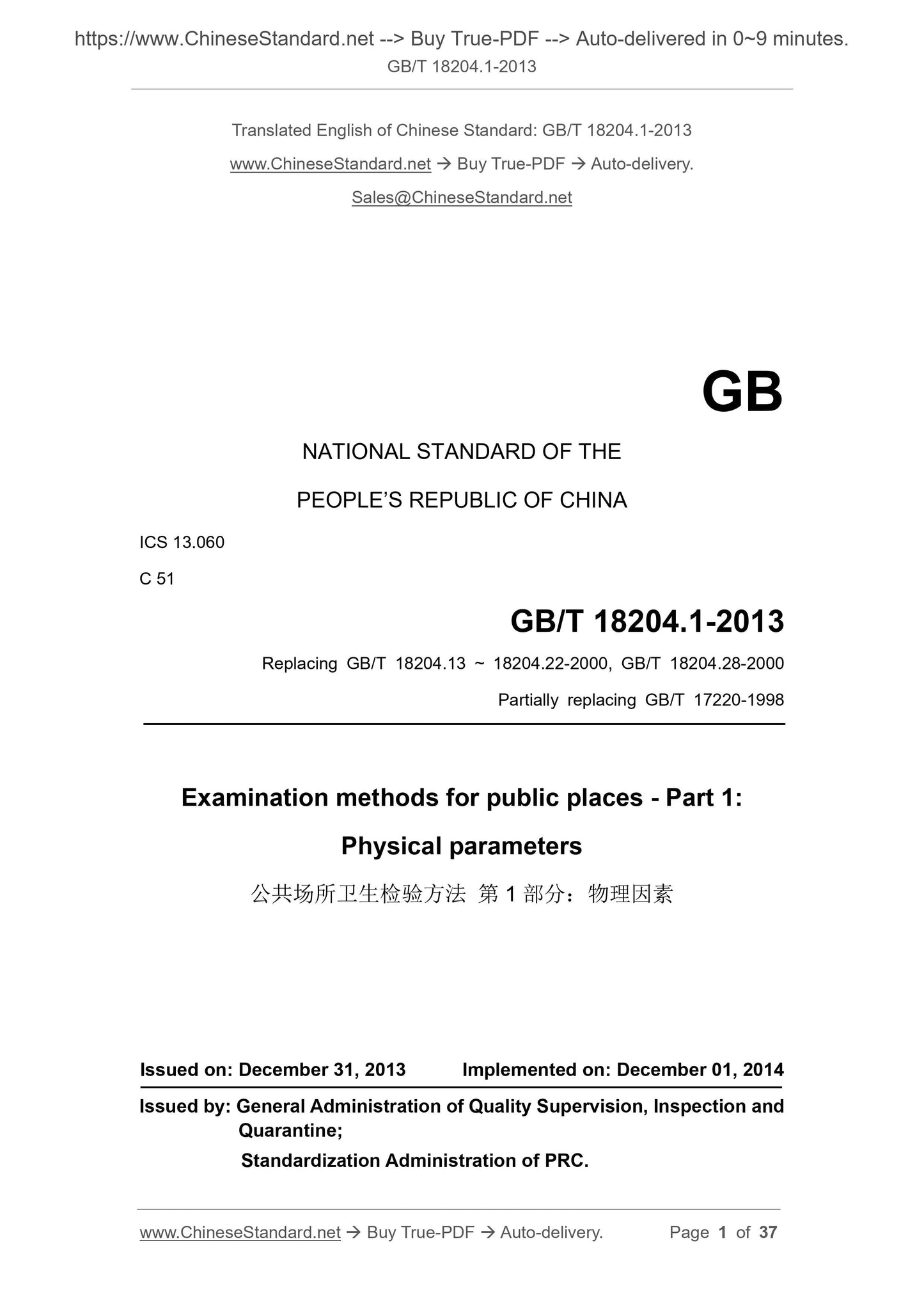
GB/T 18204.1-2013
GB
NATIONAL STANDARD OF THE
PEOPLE’S REPUBLIC OF CHINA
ICS 13.060
C 51
Replacing GB/T 18204.13 ~ 18204.22-2000, GB/T 18204.28-2000
Partially replacing GB/T 17220-1998
Examination methods for public places - Part 1:
Physical parameters
ISSUED ON: DECEMBER 31, 2013
IMPLEMENTED ON: DECEMBER 01, 2014
Issued by: General Administration of Quality Supervision, Inspection and
Quarantine;
Standardization Administration of PRC.
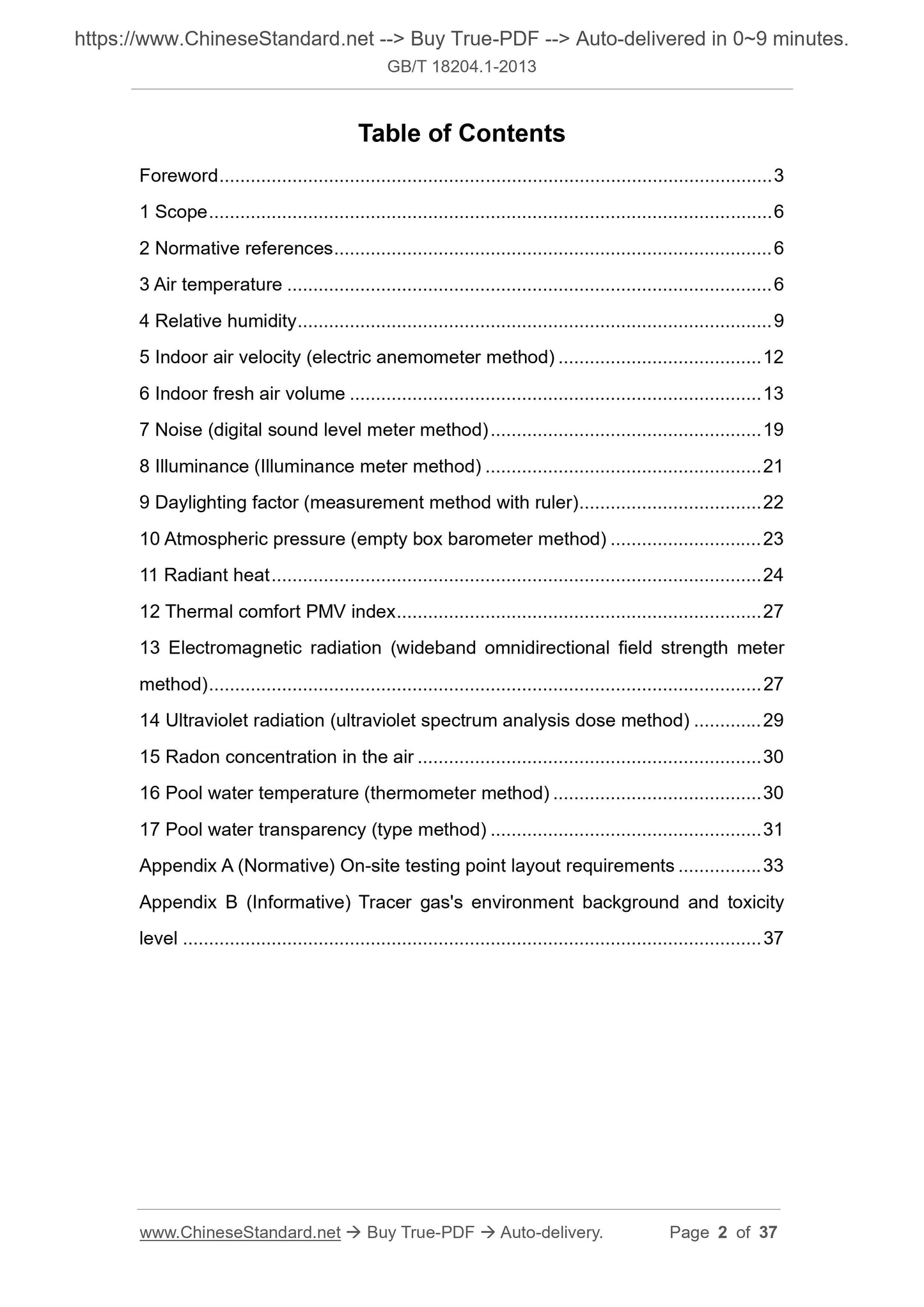
Table of Contents
Foreword ... 3
1 Scope ... 6
2 Normative references ... 6
3 Air temperature ... 6
4 Relative humidity ... 9
5 Indoor air velocity (electric anemometer method) ... 12
6 Indoor fresh air volume ... 13
7 Noise (digital sound level meter method) ... 19
8 Illuminance (Illuminance meter method) ... 21
9 Daylighting factor (measurement method with ruler) ... 22
10 Atmospheric pressure (empty box barometer method) ... 23
11 Radiant heat ... 24
12 Thermal comfort PMV index ... 27
13 Electromagnetic radiation (wideband omnidirectional field strength meter
method) ... 27
14 Ultraviolet radiation (ultraviolet spectrum analysis dose method) ... 29
15 Radon concentration in the air ... 30
16 Pool water temperature (thermometer method) ... 30
17 Pool water transparency (type method) ... 31
Appendix A (Normative) On-site testing point layout requirements ... 33
Appendix B (Informative) Tracer gas's environment background and toxicity
level ... 37
Examination methods for public places - Part 1:
Physical parameters
1 Scope
This part of GB/T 18204 specifies the measurement method of physical factors
in public places.
This part applies to the determination of physical factors in public places, other
places, rooms and other indoor environments can be implemented with
reference to this part.
Note: In addition to the fresh air volume testing method in this part, if there are two or
more testing methods for the same indicator, they can be selected according to
technical conditions, but the first method is the arbitration method.
2 Normative references
The following documents are essential to the application of this document. For
the dated documents, only the versions with the dates indicated are applicable
to this document; for the undated documents, only the latest version (including
all the amendments) is applicable to this standard.
GB/T 18049 Moderate thermal environments - Determination of the PMV
and PPD indices and specification of the conditions for thermal comfort
GB/T 18883-2002 Indoor air quality standard
HJ/T 10.2 Guideline on management of radioactive environmental protection
- Electromagnetic radiation monitoring - Instruments and methods
3 Air temperature
3.1 Glass liquid thermometer method
3.1.1 Principle
The glass liquid thermometer is composed of a thin-walled temperature bulb
containing the liquid of the thermometer and a thin glass tube sealed and
connected with the temperature bulb. The change of air temperature will cause
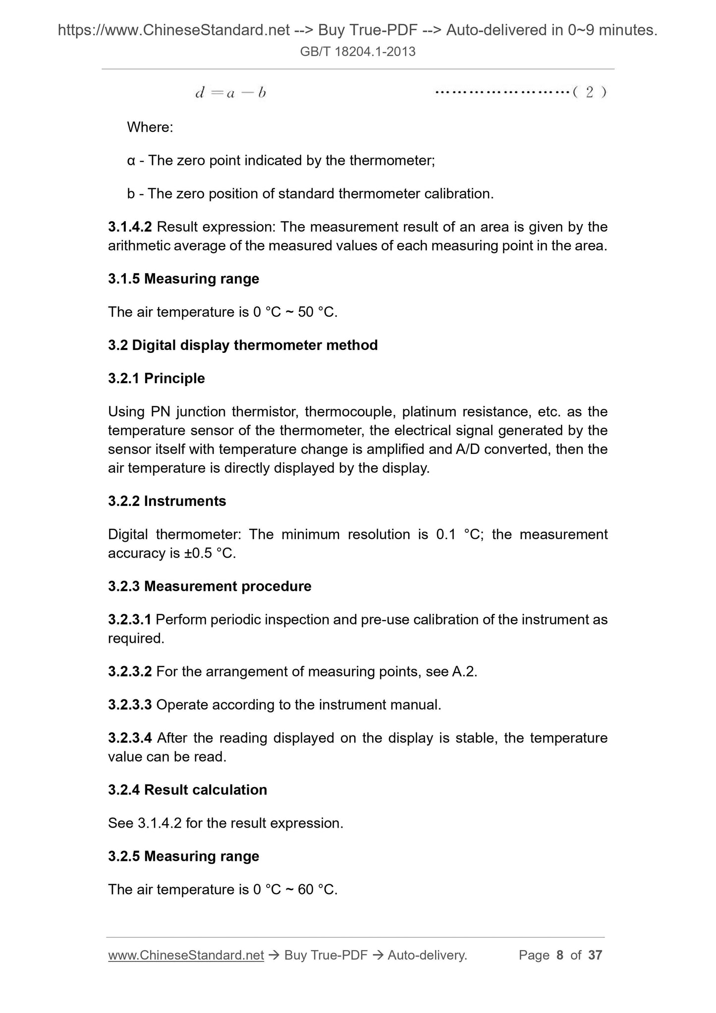
Where:
α - The zero point indicated by the thermometer;
b - The zero position of standard thermometer calibration.
3.1.4.2 Result expression: The measurement result of an area is given by the
arithmetic average of the measured values of each measuring point in the area.
3.1.5 Measuring range
The air temperature is 0 °C ~ 50 °C.
3.2 Digital display thermometer method
3.2.1 Principle
Using PN junction thermistor, thermocouple, platinum resistance, etc. as the
temperature sensor of the thermometer, the electrical signal generated by the
sensor itself with temperature change is amplified and A/D converted, then the
air temperature is directly displayed by the display.
3.2.2 Instruments
Digital thermometer: The minimum resolution is 0.1 °C; the measurement
accuracy is ±0.5 °C.
3.2.3 Measurement procedure
3.2.3.1 Perform periodic inspection and pre-use calibration of the instrument as
required.
3.2.3.2 For the arrangement of measuring points, see A.2.
3.2.3.3 Operate according to the instrument manual.
3.2.3.4 After the reading displayed on the display is stable, the temperature
value can be read.
3.2.4 Result calculation
See 3.1.4.2 for the result expression.
3.2.5 Measuring range
The air temperature is 0 °C ~ 60 °C.
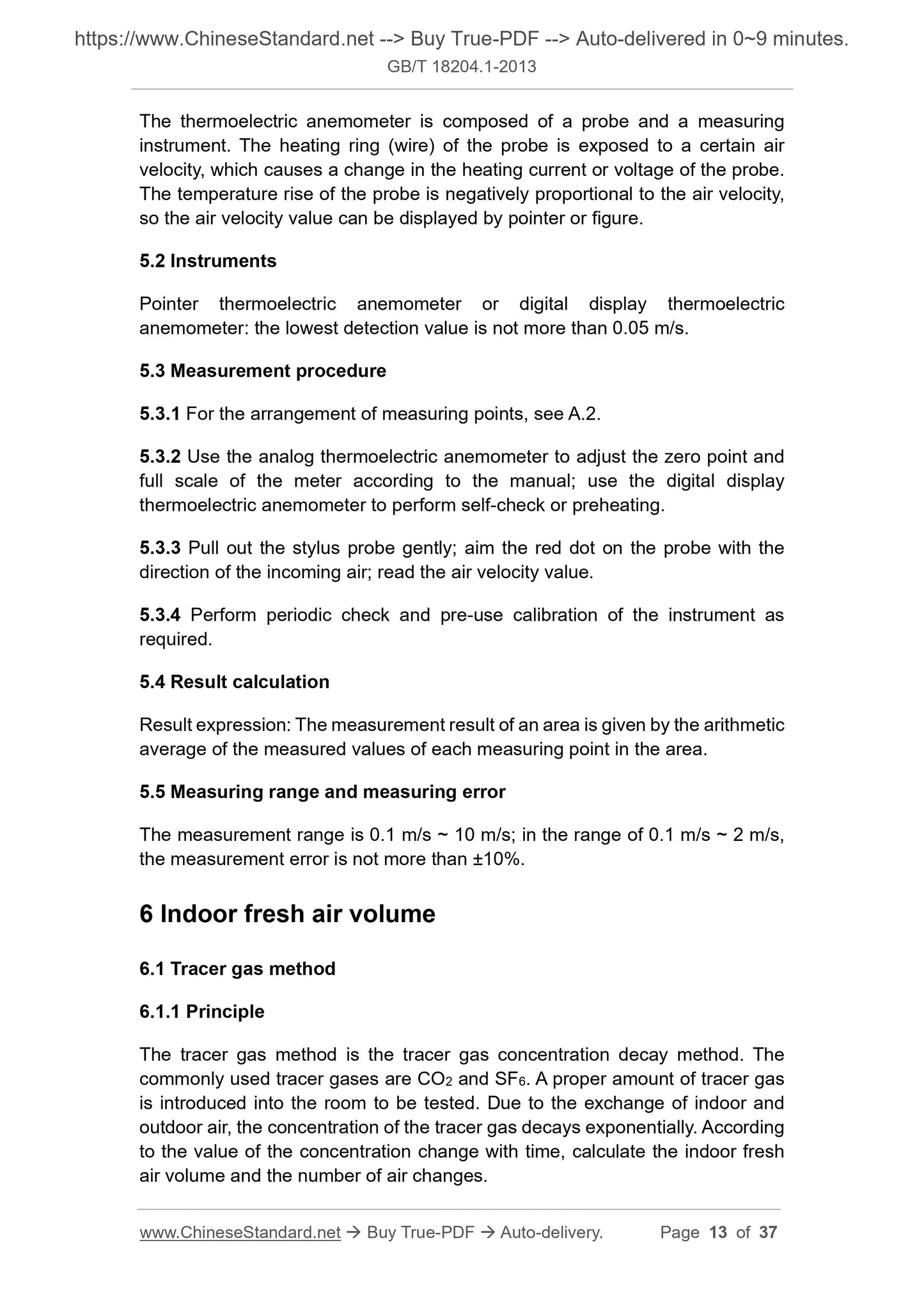
The thermoelectric anemometer is composed of a probe and a measuring
instrument. The heating ring (wire) of the probe is exposed to a certain air
velocity, which causes a change in the heating current or voltage of the probe.
The temperature rise of the probe is negatively proportional to the air velocity,
so the air velocity value can be displayed by pointer or figure.
5.2 Instruments
Pointer thermoelectric anemometer or digital display thermoelectric
anemometer: the lowest detection value is not more than 0.05 m/s.
5.3 Measurement procedure
5.3.1 For the arrangement of measuring points, see A.2.
5.3.2 Use the analog thermoelectric anemometer to adjust the zero point and
full scale of the meter according to the manual; use the digital display
thermoelectric anemometer to perform self-check or preheating.
5.3.3 Pull out the stylus probe gently; aim the red dot on the probe with the
direction of the incoming air; read the air velocity value.
5.3.4 Perform periodic check and pre-use calibration of the instrument as
required.
5.4 Result calculation
Result expression: The measurement result of an area is given by the arithmetic
average of the measured values of each measuring point in the area.
5.5 Measuring range and measuring error
The measurement range is 0.1 m/s ~ 10 m/s; in the range of 0.1 m/s ~ 2 m/s,
the measurement error is not more than ±10%.
6 Indoor fresh air volume
6.1 Tracer gas method
6.1.1 Principle
The tracer gas method is the tracer gas concentration decay method. The
commonly used tracer gases are CO2 and SF6. A proper amount of tracer gas
is introduced into the room to be tested. Due to the exchange of indoor and
outdoor air, the concentration of the tracer gas decays exponentially. According
to the value of the concentration change with time, calculate the indoor fresh
air volume and the number of air changes.
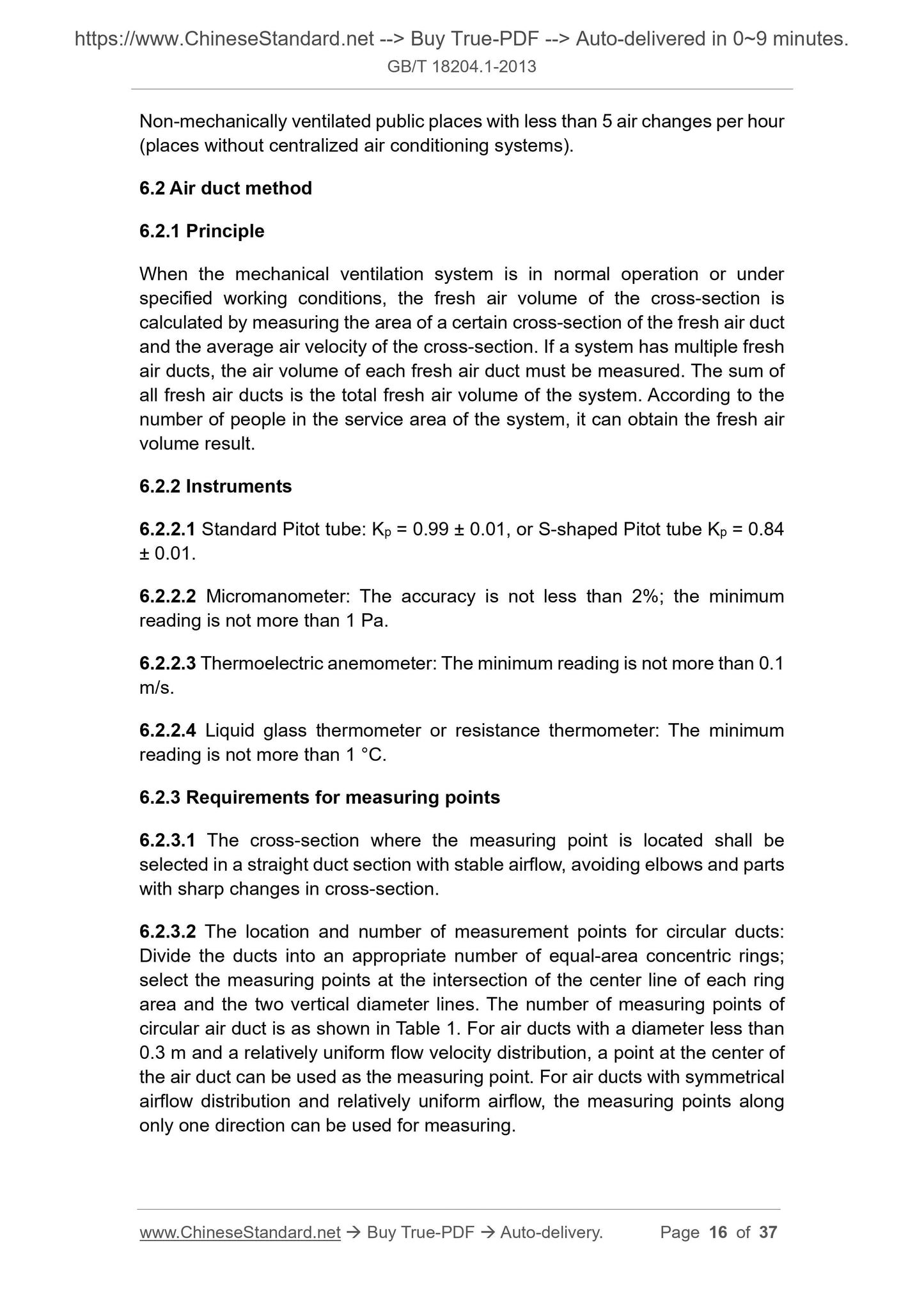
Non-mechanically ventilated public places with less than 5 air changes per hour
(places without centralized air conditioning systems).
6.2 Air duct method
6.2.1 Principle
When the mechanical ventilation system is in normal operation or under
specified working conditions, the fresh air volume of the cross-section is
calculated by measuring the area of a certain cross-section of the fresh air duct
and the average air velocity of the cross-section. If a system has multiple fresh
air ducts, the air volume of each fresh air duct must be measured. The sum of
all fresh air ducts is the total fresh air volume of the system. According to the
number of people in the service area of the system, it can obtain the fresh air
volume result.
6.2.2 Instruments
6.2.2.1 Standard Pitot tube: Kp = 0.99 ± 0.01, or S-shaped Pitot tube Kp = 0.84
± 0.01.
6.2.2.2 Micromanometer: The accuracy is not less than 2%; the minimum
reading is not more than 1 Pa.
6.2.2.3 Thermoelectric anemometer: The minimum reading is not more than 0.1
m/s.
6.2.2.4 Liquid glass thermometer or resistance thermometer: The minimum
reading is not more than 1 °C.
6.2.3 Requirements for measuring points
6.2.3.1 The cross-section where the measuring point is located shall be
selected in a straight duct section with stable airflow, avoiding elbows and parts
with sharp changes in cross-section.
6.2.3.2 The location and number of measurement points for circular ducts:
Divide the ducts into an appropriate number of equal-area concentric rings;
select the measuring points at the intersection of the center line of each ring
area and the two vertical diameter lines. The number of measuring points of
circular air duct is as shown in Table 1. For air ducts with a diameter less than
0.3 m and a relatively uniform flow velocity distribution, a point at the center of
the air duct can be used as the measuring point. For air ducts with symmetrical
airflow distribution and relatively uniform airflow, the measuring points along
only one direction can be used for measuring.
Digital sound level meters usually use capacitive acoustic-electric transducers
to convert the measured sound signal into an electrical signal, which becomes
a sound level value after a certain amount of internal processing. Use a sound
level meter to measure a certain number of indoor environment A-weighted
sound level values within a specified time; calculate the equivalent A sound
level LAeq, which is the indoor noise value.
7.2 Instruments
Digital sound level meter: The measuring range (A sound level) is 30 dB ~ 120
dB, at an accuracy of ±1.0 dB.
7.3 Measurement procedure
7.3.1 For the arrangement of measuring points, see A.3.
7.3.2 Use a calibrator to calibrate the sound level meter before measurement.
7.3.3 The sound level meter can be hand-held or fixed on a tripod during
measurement; the effect of sound reflection shall be minimized.
7.3.4 For steady-state noise, use the sound level meter to read the indicated
value or average value for 1 min. For impulse noise, read the peak value and
pulse hold value.
7.3.5 For periodic noise, use the slow gear of the sound level meter to read an
instantaneous A sound level value every 5 s; measure a period.
7.3.6 For non-periodic non-steady-state noise, use the slow gear of the sound
level meter to read an instantaneous A sound level value every 5 s; read several
data continuously.
7.4 Calculation of results
7.4.1 If the indoor environment noise is steady-state noise, the indicated value
or average value of the sound level meter is the equivalent A sound level LAeq.
7.4.2 If the indoor environment noise is impulse noise, the peak value measured
by the sound level meter is the equivalent A sound level LAeq.
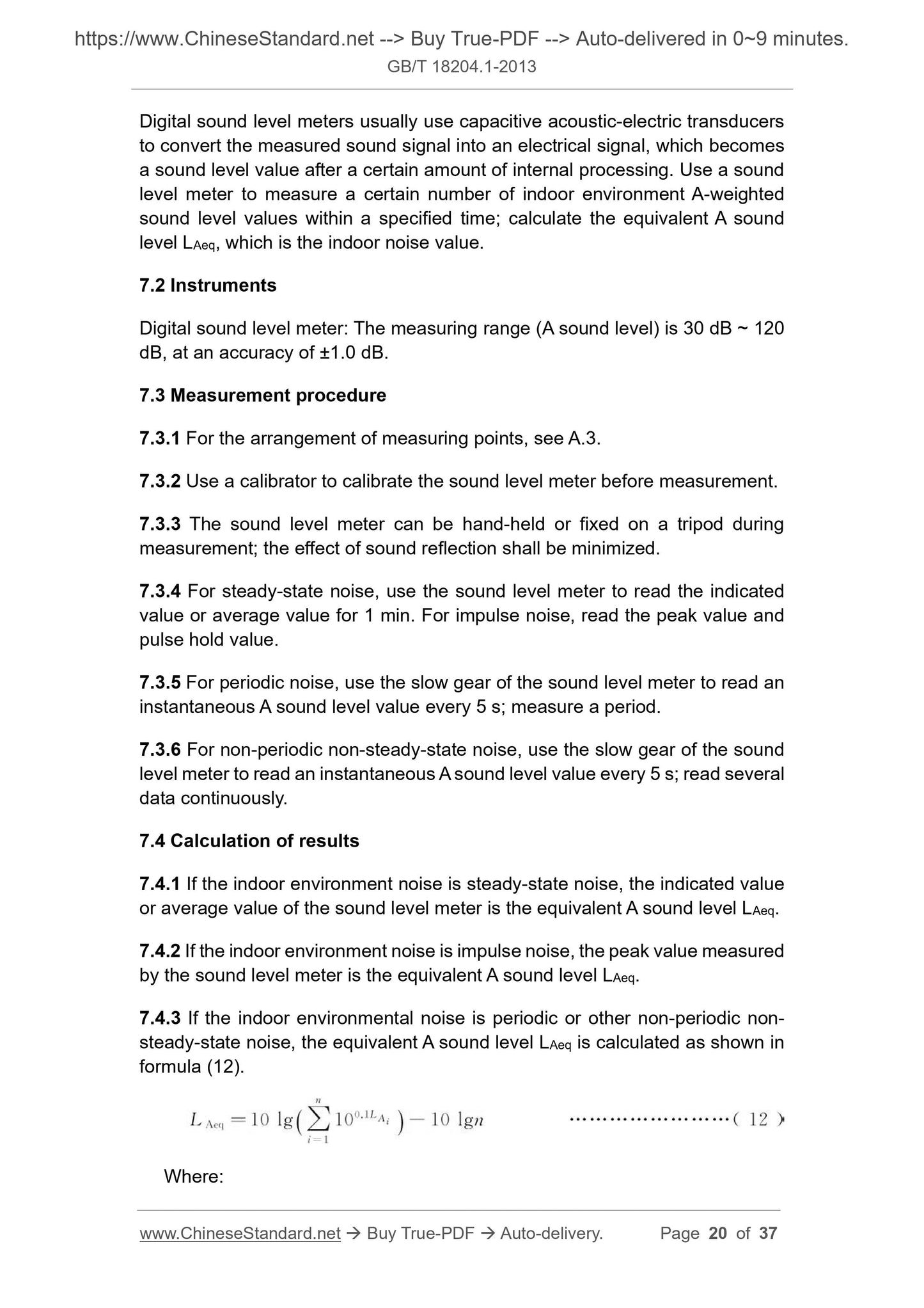
7.4.3 If the indoor environmental noise is periodic or other non-periodic non-
steady-state noise, the equivalent A sound level LAeq is calculated as shown in
formula (12).
Where:
LAeq - The equivalent A sound level of indoor environmental noise, in decibels
(dB);
n - The total number of measured data in the specified time t;
LAi - The sound level A of the ith measurement, in decibels (dB).
7.4.4 Result expression: The measurement result of an area is given by the
arithmetic mean value of the equivalent A sound level of each measuring point
in the area.
8 Illuminance (Illuminance meter method)
8.1 Principle
The illuminance meter is made using the physical photoelectric phenomenon of
photosensitive semiconductor components. When the external light hits the
photodetector (photoelectric element), the photoelectric element converts the
light energy into electric energy, then the illuminance value of the light is
displayed by the reading unit (ammeter or digital liquid crystal panel).
8.2 Instruments
Illuminance meter: The lower limit of the range is not more than 1 lx, the upper
limit is not less than 5000 lx; the error of the indication value is not more than
±8%.
8.3 Measurement procedure
8.3.1 See A.4 for the arrangement of measuring points.
8.3.2 Check and adjust the illuminance meter according to the requirements of
the instruction manual.
8.3.3 The light receiver of the illuminance meter shall be clean and dust-free.
8.3.4 The light receiver of the illuminance meter shall be placed horizontally
during measurement.
8.3.5 Place the light receiver at the position to be measured; select the range
and read the illuminance value.
8.3.6 The operator's position and clothing shall not affect the measurement
results.
8.3.7 Perform periodic verification and pre-use calibration of the instrument as
required.
10 Atmospheric pressure (empty box barometer
method)
10.1 Principle
The atmospheric pressure is measured according to the characteristics of the
compression or expansion of the metal empty box (close to the vacuum in the
box) with the change of the pressure. It consists of three parts: induction,
transmission and indication. The elastic metal empty box close to the vacuum
is balanced with an elastic sheet. Following compression or expansion, the air
pressure value can be directly indicated by passing the extension motion to the
pointer through the transfer amplification.
10.2 Instruments
Ordinary empty box barometer: Sensitivity is 0.5 hPa, accuracy is ±2 hPa;
plateau empty box barometer: sensitivity is 0.5 hPa, accuracy is ±3.3 hPa.
10.3 Measurement procedure
10.3.1 Perform periodic verification and pre-use calibration of the instrument as
required.
10.3.2 After opening the cover of the barometer box cover, read the attached
temperature first to an accuracy of 0.1 °C; tap the surface of the box (overcome
the mechanical friction in the barometer in the empty box); start reading after
the pointer is swing and stand still. When reading, the line of sight needs to be
perpendicular to the scale surface; the value shown on the tip of the reading
pointer shall be accurate to 0.1 hPa.
10.4 Result calculation
The calculation of atmospheric pressure is as shown in formula (14).
Where:
P - Atmospheric pressure, the unit is Pascals (Pa);
P1 - Scale correction value, as given in the instrument manual, the unit is
Pascals (Pa);
P2 - Temperature correction value, the unit is Pascals (Pa);
P3 - Supplementary correction value, as given in the verification certificate,
σ - Stephen Boltzmann's constant, 5.67 × 10⁻⁸ W/m2.
Note: Do not touch the metal part of the probe with your hands during the
measurement, to ensure the accuracy of the test.
11.2 Black bulb thermometer
11.2.1 Principle
The radiant heat in the environment is absorbed by the black-painted copper
ball, which increases the temperature in the copper bulb. The temperature in
the copper bulb is measured by a thermometer, meanwhile the air temperature
a...
Share
