Skip to product information
1 of 12

PayPal, credit cards. Download editable-PDF and invoice in 1 second!

GB/T 50312-2016 English PDF (GB/T50312-2016)

GB/T 50312-2016 English PDF (GB/T50312-2016)

Regular price $1,520.00
Regular price Sale price $1,520.00
Sale Sold out
Shipping calculated at checkout.
GB/T 50312-2016: Code for engineering acceptance of generic cabling system
Delivery: 9 seconds. Download (& Email) true-PDF + Invoice.
Get Quotation: Click GB/T 50312-2016 (Self-service in 1-minute)
Historical versions (Master-website): GB/T 50312-2016
Preview True-PDF (Reload/Scroll-down if blank)

GB/T 50312-2016
GB
NATIONAL STANDARD OF THE
PEOPLE’S REPUBLIC OF CHINA
UDC
P GB/T 50312-2016
Code for engineering acceptance of generic cabling system
ISSUED ON: AUGUST 26, 2016
IMPLEMENTED ON: APRIL 01, 2017
Issued by: Ministry of Housing and Urban-Rural Development of PRC.
General Administration of Quality Supervision, Inspection and
Quarantine of PRC.
Table of Contents
Foreword ... 5
1 General provisions ... 7
2 Abbreviation ... 7
3 Environment examination ... 8
4 Examination of equipment and test instrumentation ... 10
5 Examination of equipment installation ... 13
6 Examination of cable laying and protective measures ... 15
6.1 Cable laying ... 15
6.2 Protective measures ... 19
7 Cable termination ... 22
8 Engineering electrical testing ... 25
9 Management system acceptance ... 28
10 Engineering acceptance ... 30
Appendix A Engineering inspection contents ... 33
Appendix B Engineering electrical testing methods and contents ... 37
Appendix C Fiber channel and link testing ... 57
Explanation of wording in this code ... 60
List of quoted standards ... 61
Code for engineering acceptance of generic cabling system
1 General provisions
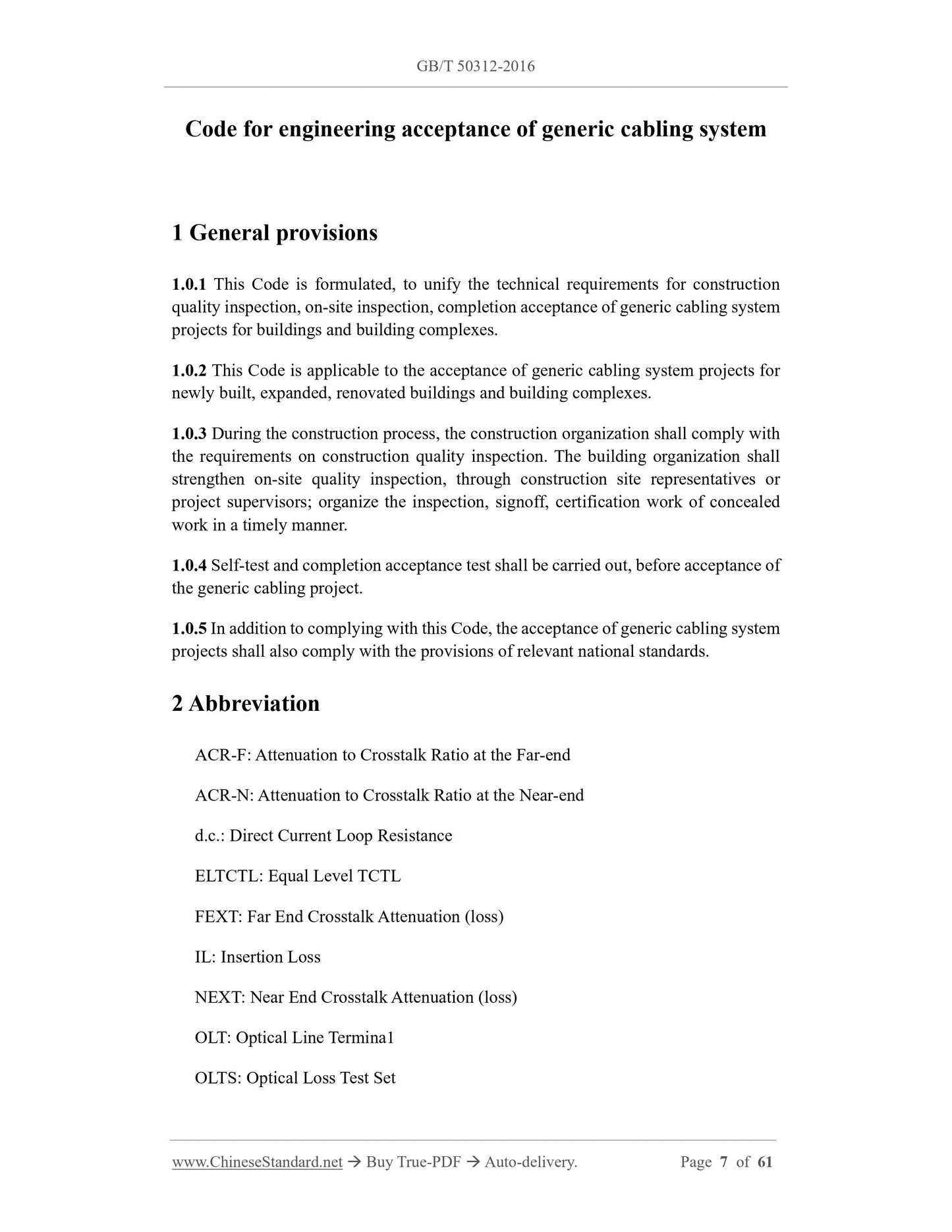
1.0.1 This Code is formulated, to unify the technical requirements for construction
quality inspection, on-site inspection, completion acceptance of generic cabling system
projects for buildings and building complexes.
1.0.2 This Code is applicable to the acceptance of generic cabling system projects for
newly built, expanded, renovated buildings and building complexes.
1.0.3 During the construction process, the construction organization shall comply with
the requirements on construction quality inspection. The building organization shall
strengthen on-site quality inspection, through construction site representatives or
project supervisors; organize the inspection, signoff, certification work of concealed
work in a timely manner.
1.0.4 Self-test and completion acceptance test shall be carried out, before acceptance of
the generic cabling project.
1.0.5 In addition to complying with this Code, the acceptance of generic cabling system
projects shall also comply with the provisions of relevant national standards.
2 Abbreviation
ACR-F: Attenuation to Crosstalk Ratio at the Far-end
ACR-N: Attenuation to Crosstalk Ratio at the Near-end
d.c.: Direct Current Loop Resistance
ELTCTL: Equal Level TCTL
FEXT: Far End Crosstalk Attenuation (loss)
IL: Insertion Loss
NEXT: Near End Crosstalk Attenuation (loss)
OLT: Optical Line Termina1
OLTS: Optical Loss Test Set
OTDR: Optical Time Domain Reflectometer
PS NEXT: Power Sum Near End Crosstalk Attenuation (loss)
PS AACR-F: Power Sum Attenuation to Alien Crosstalk Ratio at the Far-end
PS AACR-Favg: Average Power Sum Attenuation to Alien Crosstalk Ratio at the
Far-end
PS ACR-F: Power Sum Attenuation to Crosstalk Ratio at the Far-end
PS ACR-N: Power Sum Attenuation to Crosstalk Ratio at the Near-end
PS ANEXT: Power Sum Alien Near-End Crosstalk (loss)
PS ANEXTavg: Average Power Sum Alien Near-End Crosstalk (loss)
PS FEXT: Power Sum Far End Crosstalk
RL: Return Loss
TCL: Transverse Conversion Loss
TCTL: Transverse Conversion Transfer Loss
3 Environment examination
3.0.1 The building environment examination of work areas, telecommunications rooms,
equipment rooms, etc. shall comply with the following requirements:
1 The civil works in the work area, telecommunications room, equipment room, user
unit area shall be completed. The floor of the building shall be flat and smooth; the
height and width of the door shall comply with the requirements of design
document.
2 The location, quantity, size of embedded trough boxes, concealed conduits, holes,
shafts in the building shall comply with the requirements of design document.
3 Where the raised floor is laid, the anti-static measures and earthing of the raised
floor shall comply with the requirements of design document.
4 The height -- from the bottom of the information socket box, which is concealed
or exposed on the wall or column to the ground -- should be 300 mm.
5 The height -- from the bottom of the information socket box, which is installed on
the side partition of the workbench to the adjacent wall -- should be 1000 mm.
6 The CP assembly point box and multi-user information socket box should be
installed on the inlet side of the duct, as well as on columns and load-bearing walls,
which are easy for maintenance. The height of the bottom edge of the box, above
the ground, should be 500 mm. When installed on the upper part of the wall or
column OR when installed in a suspended ceiling, the height from the ground
should not be less than 1800 mm.
7 Each work area should be equipped with no less than 2 single-phase AC 220 V/10
A power socket boxes, which have protective earthing. The power socket should
be inlaid and concealed in the wall; the height shall be consistent with the
information socket.
8 It should reserve two single-phase AC 220 V/10 A power sockets, at a level of 70
mm ~ 150 mm near the information distribution box of each user unit. The
distribution lines of each power socket shall be equipped with protective electrical
appliances. The single-phase AC 220 V power supply shall be introduced into the
wiring box. The power socket should be inlaid and concealed in the wall; the height
from the bottom to the ground should be consistent with the information wiring
box.
9 No less than 2 single-phase AC 220 V/10 A power socket boxes shall be installed
in the telecommunications room, equipment room, incoming line room. The
distribution line of each power socket shall be equipped with a protector. The power
supply of the equipment shall be configured separately. The power socket should
be inlaid and concealed in the wall; the height from the bottom to the ground should
be 300 mm.
10 Reliable grounding equipotential bonding terminal boards shall be provided, in
telecommunications rooms, equipment rooms, incoming line rooms, weak current
shafts. The grounding resistance value and grounding wire specifications shall
meet the design requirements.
11 Factors such as the location, area, height, ventilation, fire protection,
environmental temperature, humidity of telecommunications rooms, equipment
rooms, incoming line rooms shall meet the design requirements.
3.0.2 The inspection of the building’s incoming line room and entrance facilities shall
meet the following requirements:
1 The number, combination and arrangement of incoming pipes, as well as the
location and spacing between other facilities, such as electrical, water, gas, sewers,
etc., shall comply with the requirements of the design documents;
2 The laying method used for incoming cables shall comply with the requirements
of the design documents;
3 The treatment of the pipeline inlet shall meet the design requirements; measures
5 Metal pipe troughs shall be galvanized or otherwise anti-corrosion treated,
according to the requirements of the engineering environment. Plastic pipe troughs
shall be flame-retardant pipe troughs; the outer walls shall have flame-retardant
markings;
6 The materials and specifications of various metal parts shall meet the quality
requirements; there shall be no skew, twist, burr, break or damage;
7 The surface treatment and plating of metal parts shall be uniform and complete;
the surface shall be smooth, without defects such as falling off or blisters.
4.0.3 The inspection of cables shall comply with the following requirements:
1 The types and specifications of cables and optical cables used in the project as well
as the flame retardant grade of the cables shall comply with the requirements of the
design documents.
2 The cable's exit-factory quality inspection report, certificate, exit-factory test
record and other accompanying materials shall be complete. The attached signs and
labels shall be complete and clear; the outer packaging shall indicate the model and
specifications.
3 The outer packaging and outer sheath of the cable must be intact. When the outer
packaging of the panel or box is seriously damaged, it shall be inspected according
to the cable product requirements; used in the project after passing the test.
4 The cables shall be accompanied by an electrical performance inspection report
for this batch. Before construction, the cable lengths and index parameters of the
panels and boxes shall be randomly inspected, according to cable product standards.
The provided equipment cables and jumpers shall also be randomly inspected; the
test records shall be made.
5 After opening the optical cable, it shall first check whether the end seal of optical
cable is in good condition. When the optical cable’s outer packaging or optical
cable sheath is damaged, the optical fiber cable shall be tested for optical fiber
performance indexes, which shall comply with the following requirements:
1) When there is fiber breakage, it shall be processed and used after passing the
inspection;
2) The markings on ends A and B of the optical cable shall be correct and obvious;
3) After the fiber testing is completed, the end shall be sealed and fixed; the outer
packaging shall be restored.
6 Single-coil of optical cables shall be tested for length of each optical fiber.
7 The inspection of optical fiber splicing cords or optical jumpers shall comply with
the following requirements:
1) The end faces of the optical fiber connecting devices at both ends shall be
equipped with appropriate protective caps;
2) Optical fibers shall have obvious type markings; they shall comply with the
requirements of design document;
3) Use an optical fiber end-face tester to randomly inspect the end faces of the
batch of optical connection devices; the proportion should not be greater than
5% ~ 10%.
4.0.4 The inspection of connecting devices shall comply with the following
requirements:
1 The components of wiring modules, information socket modules and other
connecting devices shall be complete; the electrical and mechanical performance
and other indicators shall comply with the quality standards of the corresponding
products. Plastic materials shall be flame retardant AND meet design requirements.
2 The type, quantity, port location of optical fiber connecting devices and adapters
shall be consistent with the design. Optical fiber connecting devices shall have a
smooth and clean appearance, without defects such as oil stains, burrs, scars, cracks;
the combination of various components shall be tight and smooth.
4.0.5 The use of cabling equipment shall comply with the following requirements:
1 The types and specifications of optical and cabling equipment shall comply with
the requirements of the design documents;
2 The arrangement and label names of optical and cabling equipment shall be
consistent with the design. The names of various signs shall be unified; the position
of the signs shall be correct and clear.
4.0.6 The inspection of test instruments and tools shall comply with the following
requirements:
1 Instruments and tools that need to be used in the project shall be tested or inspected
in advance. Cable testing instruments shall be accompanied by certification
documents from the testing agency.
2 The test instrument shall be able to test various electrical performance and
transmission characteristics of the corresponding cabling level; its accuracy shall
meet the corresponding requirements. The accuracy of the test instrument shall be
regularly inspected and calibrated, according to the corresponding identification
procedures and calibration methods. It can only be used within the validity period,
4 The opening and closing of the door lock shall be flexible and reliable;
5 Cabinets, wiring boxes, bridges and other equipment shall be installed firmly.
When there are seismic requirements, they shall be reinforced according to seismic
design.
5.0.2 The installation of various wiring components shall comply with the following
requirements:
1 All components shall be complete, installed in place; the marking shall be complete
and clear;
2 The mounting screws shall be tightened; the panel shall remain on a flat surface.
5.0.3 The installation of information socket modules shall comply with the following
requirements:
1 The installation position and height of the information socket bottom box, multi-
user information socket, assembly point wiring box, user unit information wiring
box shall comply with the requirements of design document.
2 When installed in the raised floor or on the ground, it shall be fixed in the junction
box. The socket panel shall be upright or horizontal. The junction box cover can be
opened and shall be waterproof, dustproof, pressure-resistant. The junction box
cover shall be flush with the ground.
3 When the information socket module and power socket are installed in the bottom
box of the information socket at the same time, the spacing and protective measures
taken shall comply with the requirements of design document.
4 The fixing method of the surface-mounted information socket bottom box shall be
determined, according to the construction site conditions.
5 The fixing screws shall be tightened; they shall not be loose.
6 Various socket panels shall be marked with colors, graphics, text, to indicate the
service type of the connected terminal equipment.
7 The optical fiber connecting devices and adapter installation bottom boxes for
terminating optical cables in the work area shall have space. They shall meet the
requirements of the design documents.
5.0.4 The installation of cable trays shall comply with the following requirements:
1 The installation position shall comply with the requirements of the construction
drawing; the left and right deviation shall not exceed 50 mm;
2 The installation level deviation shall not exceed 2 mm per meter;
3 Vertical installation shall be kept perpendicular to the ground; the perpendicularity

View full details