Skip to product information
1 of 12

www.ChineseStandard.us -- Field Test Asia Pte. Ltd.

GB/T 36544-2018 English PDF (GB/T36544-2018)

GB/T 36544-2018 English PDF (GB/T36544-2018)

Regular price $255.00
Regular price Sale price $255.00
Sale Sold out
Shipping calculated at checkout.
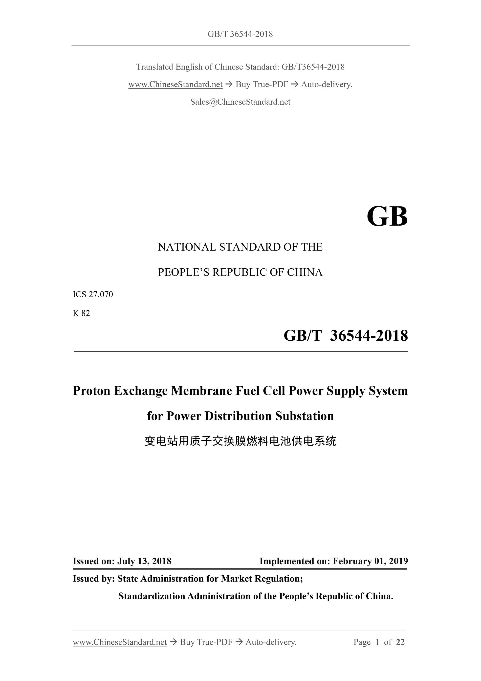
GB/T 36544-2018: Proton exchange membrane fuel cell power supply system for power distribution substation
Delivery: 9 seconds. Download (& Email) true-PDF + Invoice.
Get Quotation: Click GB/T 36544-2018 (Self-service in 1-minute)
Historical versions (Master-website): GB/T 36544-2018
Preview True-PDF (Reload/Scroll-down if blank)

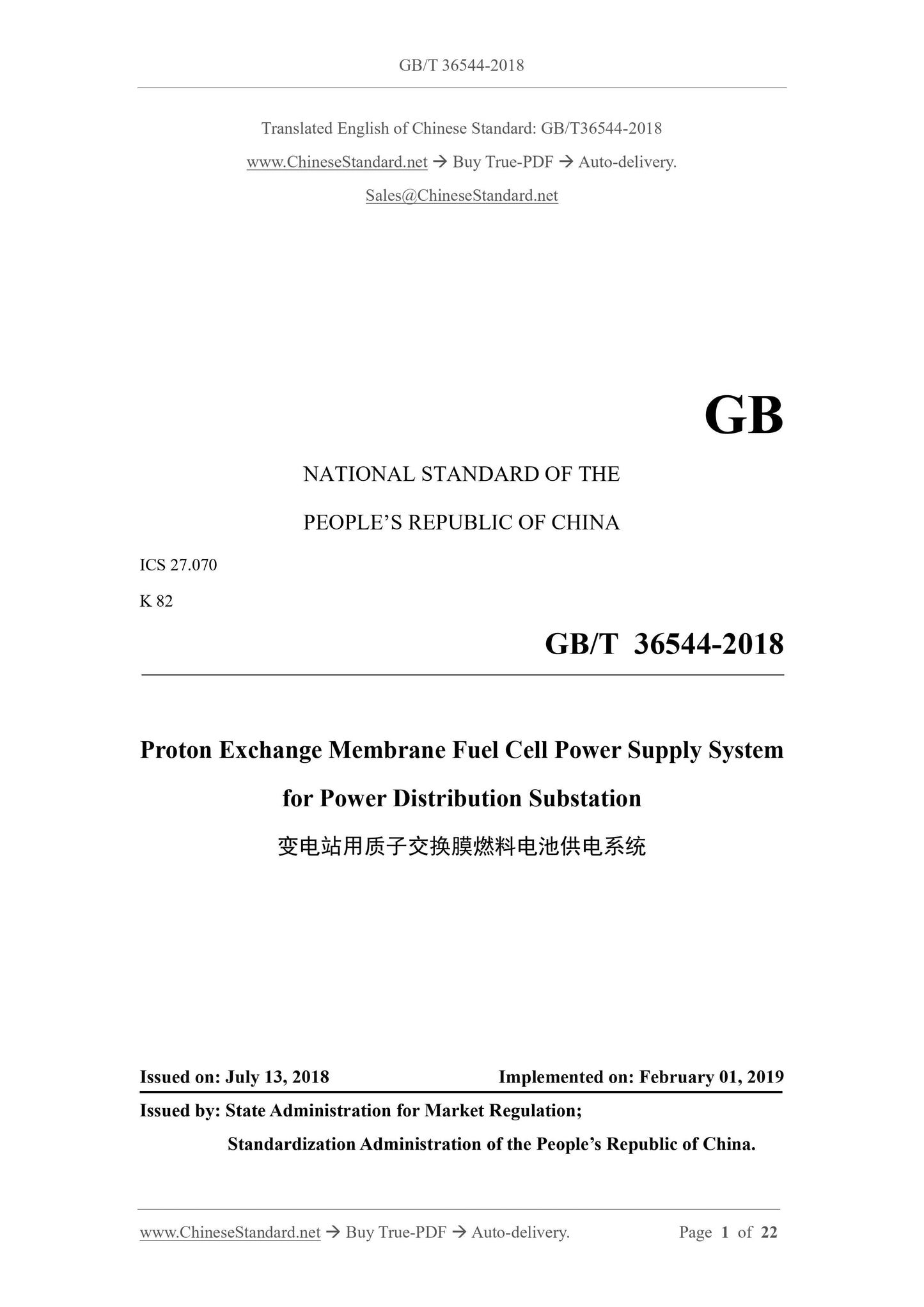
GB/T 36544-2018
NATIONAL STANDARD OF THE
PEOPLE’S REPUBLIC OF CHINA
ICS 27.070
K 82
Proton Exchange Membrane Fuel Cell Power Supply System
for Power Distribution Substation
ISSUED ON: JULY 13, 2018
IMPLEMENTED ON: FEBRUARY 01, 2019
Issued by: State Administration for Market Regulation;
Standardization Administration of the People’s Republic of China.
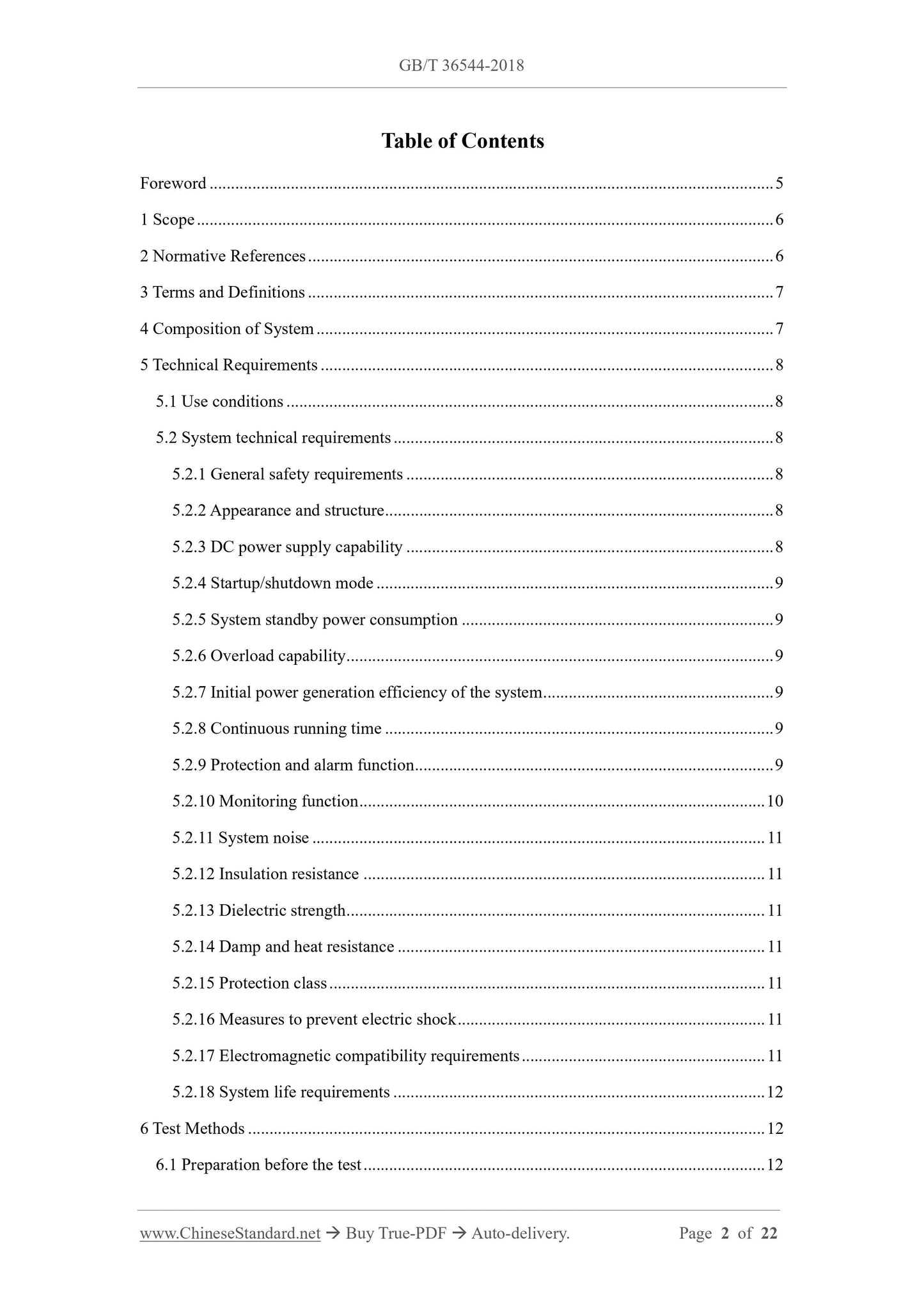
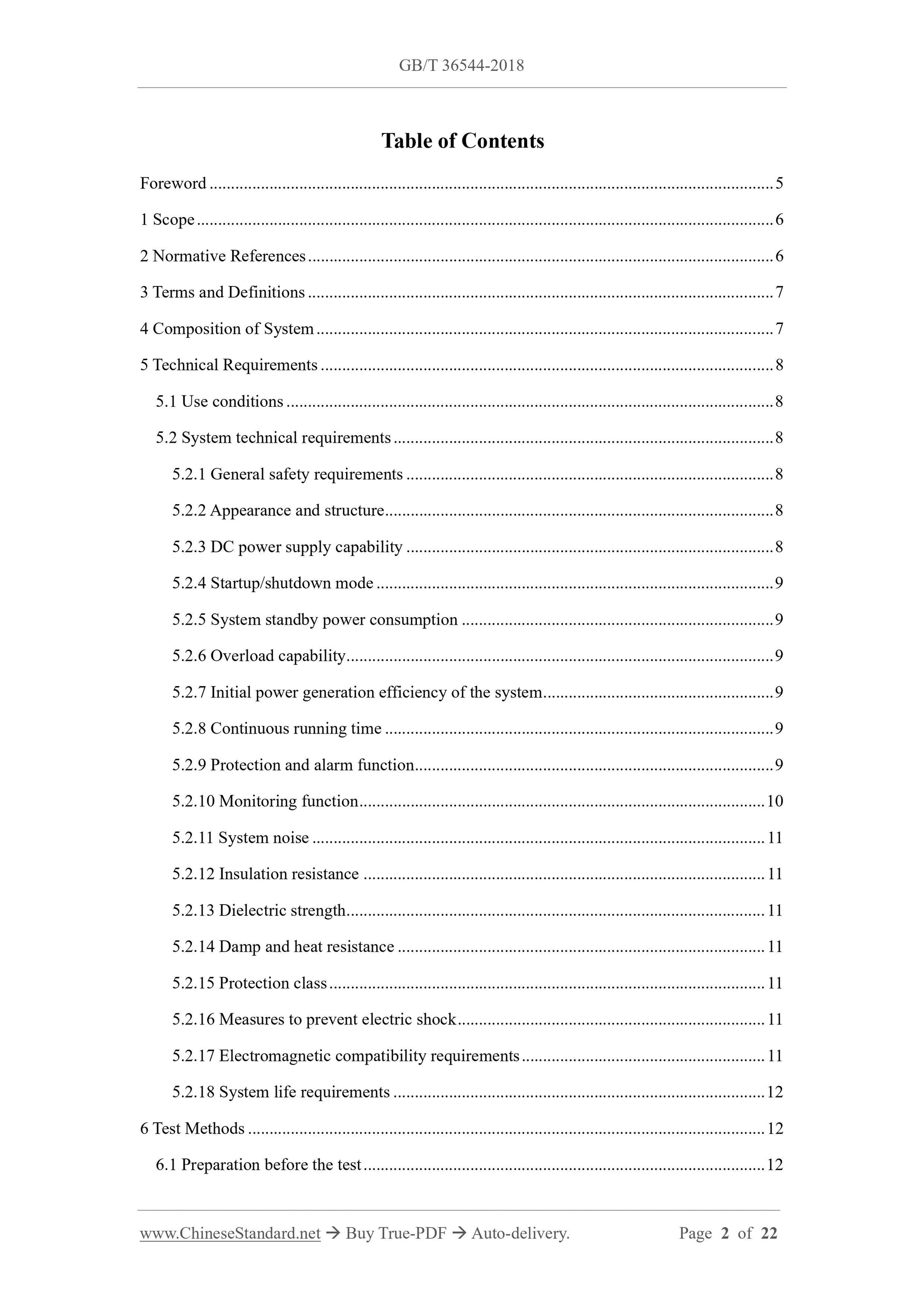
Table of Contents
Foreword ... 5
1 Scope ... 6
2 Normative References ... 6
3 Terms and Definitions ... 7
4 Composition of System ... 7
5 Technical Requirements ... 8
5.1 Use conditions ... 8
5.2 System technical requirements ... 8
5.2.1 General safety requirements ... 8
5.2.2 Appearance and structure ... 8
5.2.3 DC power supply capability ... 8
5.2.4 Startup/shutdown mode ... 9
5.2.5 System standby power consumption ... 9
5.2.6 Overload capability ... 9
5.2.7 Initial power generation efficiency of the system ... 9
5.2.8 Continuous running time ... 9
5.2.9 Protection and alarm function ... 9
5.2.10 Monitoring function ... 10
5.2.11 System noise ... 11
5.2.12 Insulation resistance ... 11
5.2.13 Dielectric strength ... 11
5.2.14 Damp and heat resistance ... 11
5.2.15 Protection class ... 11
5.2.16 Measures to prevent electric shock ... 11
5.2.17 Electromagnetic compatibility requirements ... 11
5.2.18 System life requirements ... 12
6 Test Methods ... 12
6.1 Preparation before the test ... 12
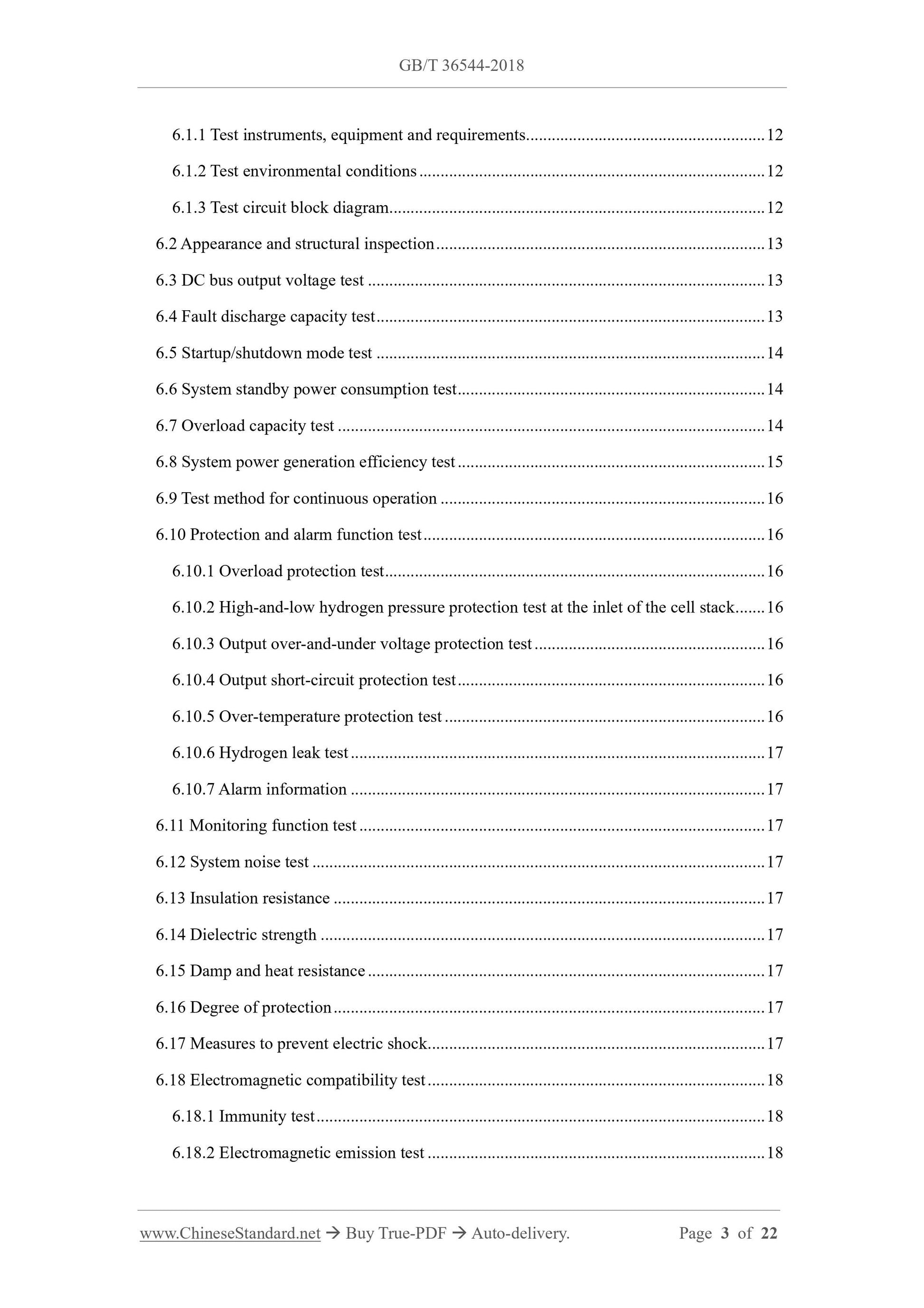
6.1.1 Test instruments, equipment and requirements ... 12
6.1.2 Test environmental conditions ... 12
6.1.3 Test circuit block diagram ... 12
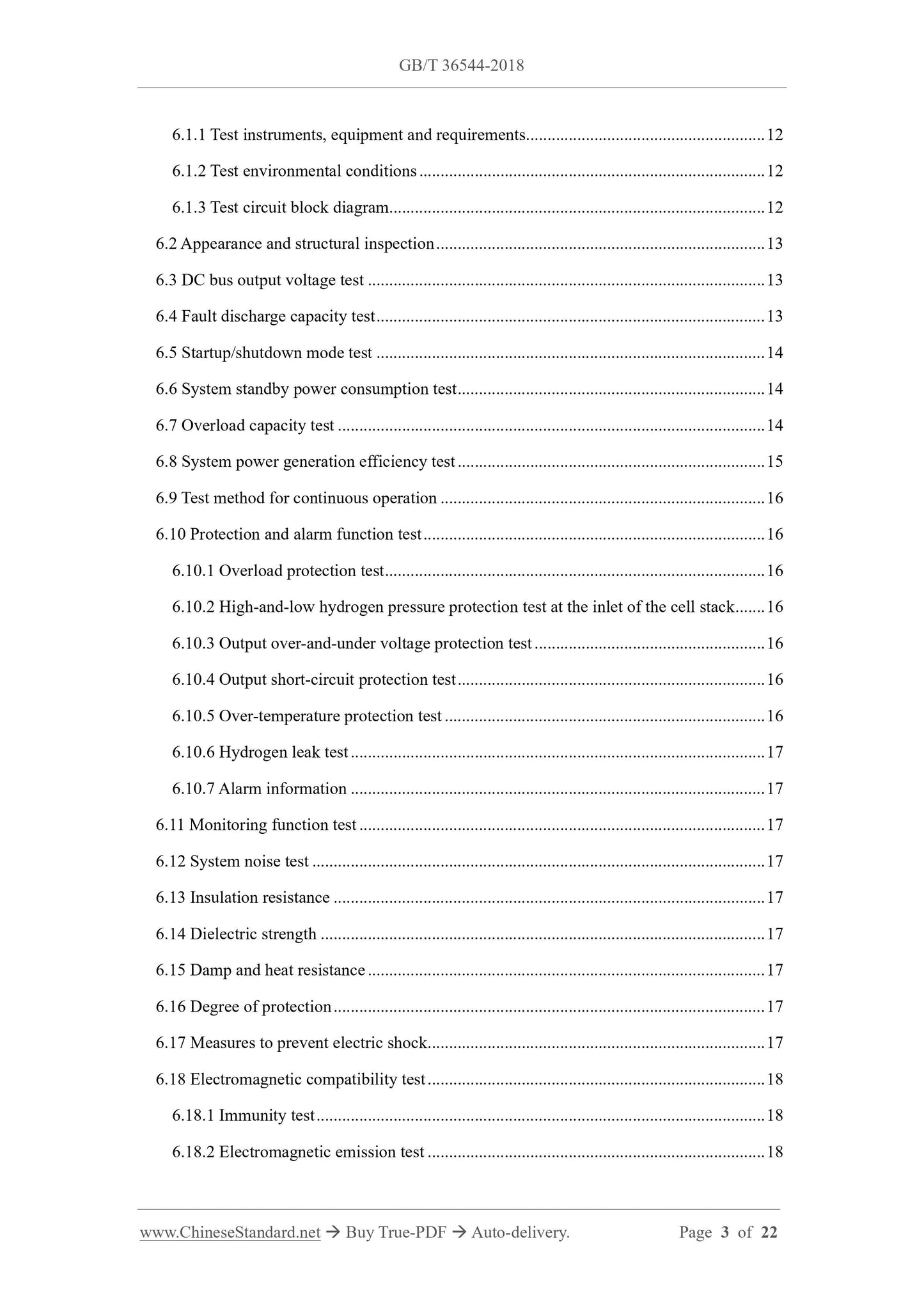
6.2 Appearance and structural inspection ... 13
6.3 DC bus output voltage test ... 13
6.4 Fault discharge capacity test ... 13
6.5 Startup/shutdown mode test ... 14
6.6 System standby power consumption test ... 14
6.7 Overload capacity test ... 14
6.8 System power generation efficiency test ... 15
6.9 Test method for continuous operation ... 16
6.10 Protection and alarm function test ... 16
6.10.1 Overload protection test ... 16
6.10.2 High-and-low hydrogen pressure protection test at the inlet of the cell stack ... 16
6.10.3 Output over-and-under voltage protection test ... 16
6.10.4 Output short-circuit protection test ... 16
6.10.5 Over-temperature protection test ... 16
6.10.6 Hydrogen leak test ... 17
6.10.7 Alarm information ... 17
6.11 Monitoring function test ... 17
6.12 System noise test ... 17
6.13 Insulation resistance ... 17
6.14 Dielectric strength ... 17
6.15 Damp and heat resistance ... 17
6.16 Degree of protection ... 17
6.17 Measures to prevent electric shock ... 17
6.18 Electromagnetic compatibility test ... 18
6.18.1 Immunity test ... 18
6.18.2 Electromagnetic emission test ... 18
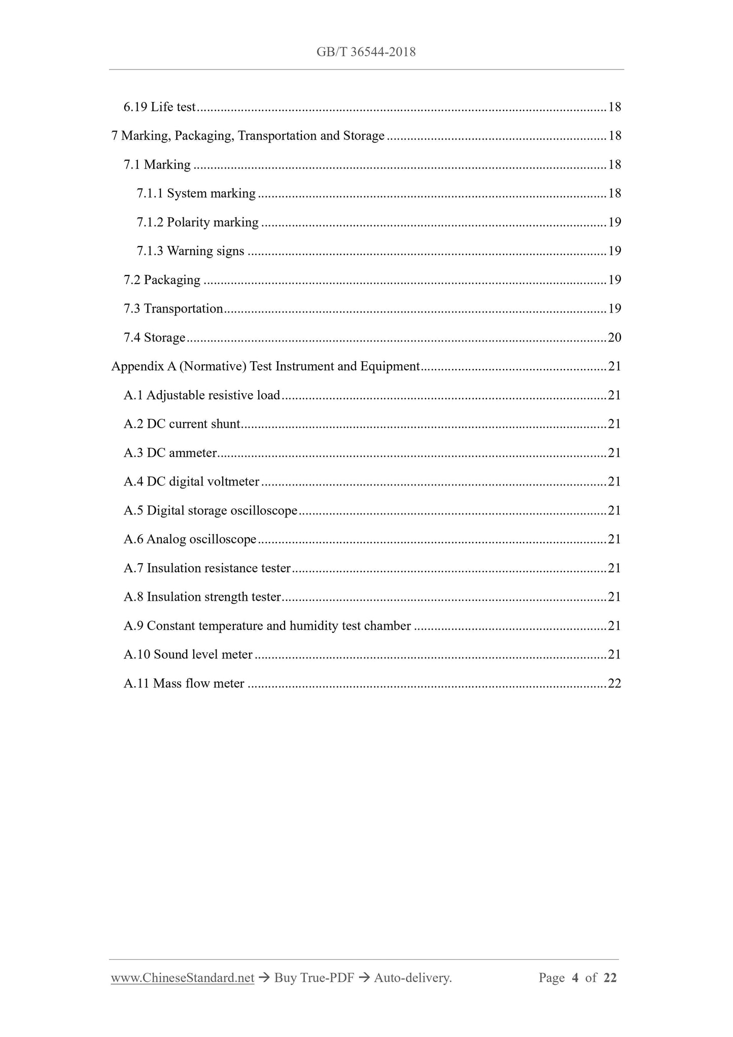
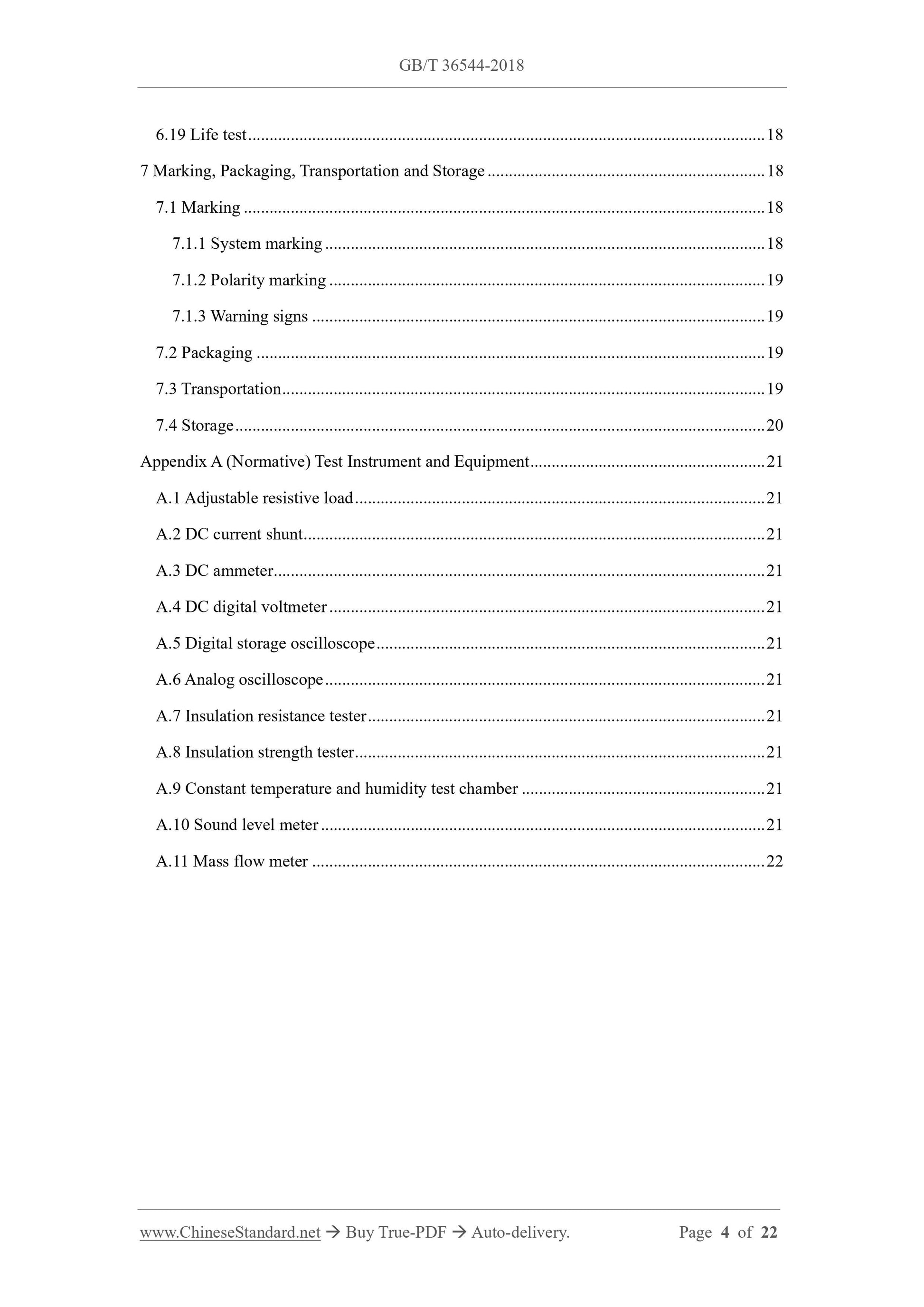
6.19 Life test ... 18
7 Marking, Packaging, Transportation and Storage ... 18
7.1 Marking ... 18
7.1.1 System marking ... 18
7.1.2 Polarity marking ... 19
7.1.3 Warning signs ... 19
7.2 Packaging ... 19
7.3 Transportation ... 19
7.4 Storage ... 20
Appendix A (Normative) Test Instrument and Equipment ... 21
A.1 Adjustable resistive load ... 21
A.2 DC current shunt ... 21
A.3 DC ammeter ... 21
A.4 DC digital voltmeter ... 21
A.5 Digital storage oscilloscope ... 21
A.6 Analog oscilloscope ... 21
A.7 Insulation resistance tester ... 21
A.8 Insulation strength tester ... 21
A.9 Constant temperature and humidity test chamber ... 21
A.10 Sound level meter ... 21
A.11 Mass flow meter ... 22
Proton Exchange Membrane Fuel Cell Power Supply System
for Power Distribution Substation
1 Scope
This Standard specifies the system composition, technical requirements, test methods, marking,
packaging, transportation and storage of the proton exchange membrane fuel cell power supply
system for power distribution substation.
This Standard applies to the proton exchange membrane fuel cell DC backup power supply
system for power distribution substation using hydrogen as fuel.
2 Normative References
The following documents are essential to the application of this document. For the dated
documents, only the versions with the dates indicated are applicable to this document; for the
undated documents, only the latest version (including all the amendments) is applicable to this
document.
GB/T 3785 (all parts) Electroacoustics – Sound Level Meters
GB/T 4208 Degrees of Protection Provided by Enclosure (IP Code)
GB/T 9254-2008 Information Technology Equipment - Radio Disturbance Characteristics
- Limits and Methods of Measurement
GB/T 19826-2014 General Specification and Safety Requirements for DC Power Supply
Equipment of Power Projects
GB/T 27748.1 Stationary Fuel Cell Power Systems - Part 1: Safety
GB/T 27748.3 Stationary Fuel Cell Power Systems – Part 3: Installation
GB/T 28816 Fuel Cell - Terminology
GB/T 31036-2014 Proton Exchange Membrane Fuel Cell Backup Power System - Safety
GB/T 31037.1-2014 Fuel Cell Power System Used for Industrial Lift Truck Applications
- Part 1: Safety
JB/T 5777.2-2002 General Specification for Control and Protection Panel (Cabinet, Desk)
of Secondary Circuit of Power System
In Figure 1, the fuel treatment system refers to the system that is composed of chemical and/or
physical treatment equipment and related heat exchangers and controllers, which are required
by the fuel cell power supply system to prepare fuel and pressurize it, if necessary.
An oxidant treatment system refers to a system that is used to meter, regulate, treat, and possibly
pressurize incoming oxidant for use by a fuel cell power supply system.
5 Technical Requirements
5.1 Use conditions
The proton exchange membrane fuel cell power supply system for substations should be able
to operate normally under the following environmental conditions:
--- The working environment temperature is: -10℃ ~ 40℃;
--- Ambient relative humidity: 10% ~ 95%, non-condensing;
--- The altitude does not exceed 2000m.
5.2 System technical requirements
5.2.1 General safety requirements
The proton exchange membrane fuel cell power supply system (hereinafter referred to as
"system") shall meet the requirements specified in GB/T 27748.1 and GB/T 27748.3.
5.2.2 Appearance and structure
The appearance and structure of the system shall meet the following requirements:
--- The appearance of the system shall be clean, without mechanical damage, and the
interface contacts shall not be rusted;
--- The surface of the system shall have product identification, and the identification shall
be clear;
--- The communication interface, power supply interface, dry contact interface, hydrogen
interface, etc. of the system shall be clearly marked.
5.2.3 DC power supply capability
5.2.3.1 DC bus output voltage
The maximum variation range of the DC bus output voltage shall be 90% ~ 110% of the nominal
voltage of the DC system.
5.2.3.2 Fault discharge capacity
After the system completes the discharge for the specified time under the rated power, the
switching-on impulse discharge test is carried out, and the impulse current is superimposed 8
times to simulate the fault current. During the three switching-on impulse discharge tests, the
output voltage of the DC bus shall be no lower than 90% of DC nominal voltage.
5.2.4 Startup/shutdown mode
The system shall have the following startup/shutdown mode:
--- Manual startup/shutdown;
--- Remote start/shutdown;
--- Auto start/shutdown.
5.2.5 System standby power consumption
The standby power consumption of the system shall be no greater than 1% of the rated output
power of the system.
NOTE: The power consumption of the fuel cell electric heating part is excluded.
5.2.6 Overload capability
When the output is 110% of the rated power, the system shall be able to run normally for 10min.
5.2.7 Initial power generation efficiency of the system
When the system outputs the rated power, the initial power generation efficiency of the system
shall be no less than 35%.
5.2.8 Continuous running time
Under the rated power, the continuous operation time of the system shall be no less than 10h;
and the instantaneous fluctuation of the output voltage of the DC bus shall be no lower than
87.5% of the nominal voltage of the index.
5.2.9 Protection and alarm function
5.2.9.1 Overload protection
When the output exceeds the rated power, the system shall be able to issue an alarm signal.
When the system is in:
--- the output is between 100% and 110% of the rated power, it lasts for 10min; or
--- the output exceeds 110% of the rated power, it lasts for 3s.
The power conversion unit shall automatically enter the output current limiting protection state,
--- Telemetry: DC bus output voltage, fuel cell system output current, hydrogen supply
pressure, fuel cell temperature, ambient temperature;
--- Remote signaling: fuel cell (cell stack/module output over/under voltage, over-
temperature, output over-current), fuel cell operation with low/high hydrogen pressure,
low/high ambient temperature, hydrogen leakage;
--- Remote control: system on/off.
5.2.11 System noise
The noise during normal operation of the system shall be no greater than 65dB.
5.2.12 Insulation resistance
The system insulation resistance shall meet the requirements of 5.3.2 in GB/T 19826-2014.
5.2.13 Dielectric strength
The system medium strength shall meet the requirements of 5.3.3 in GB/T 19826-2014.
5.2.14 Damp and heat resistance
The damp and heat resistance of the system shall meet the requirements of 5.3.6 in GB/T 19826-
2014.
5.2.15 Protection class
The protection level of the system should be no lower than IP20.
5.2.16 Measures to prevent electric shock
The measures to prevent electric shock of the system shall comply with the provisions of 5.12
in JB/T 5777.2-2002.
5.2.17 Electromagnetic compatibility requirements
5.2.17.1 Immunity requirements
The system immunity shall comply with the provisions of 5.4.1 in GB/T 19826-2014.
5.2.17.2 Electromagnetic emission limit requirements
The electromagnetic emission limit requirements refer to radiated emission limit requirements.
The radiation emission limit value of the system shall comply with the provisions of Table 12
in GB/T 19826-2014.
5.2.18 System life requirements
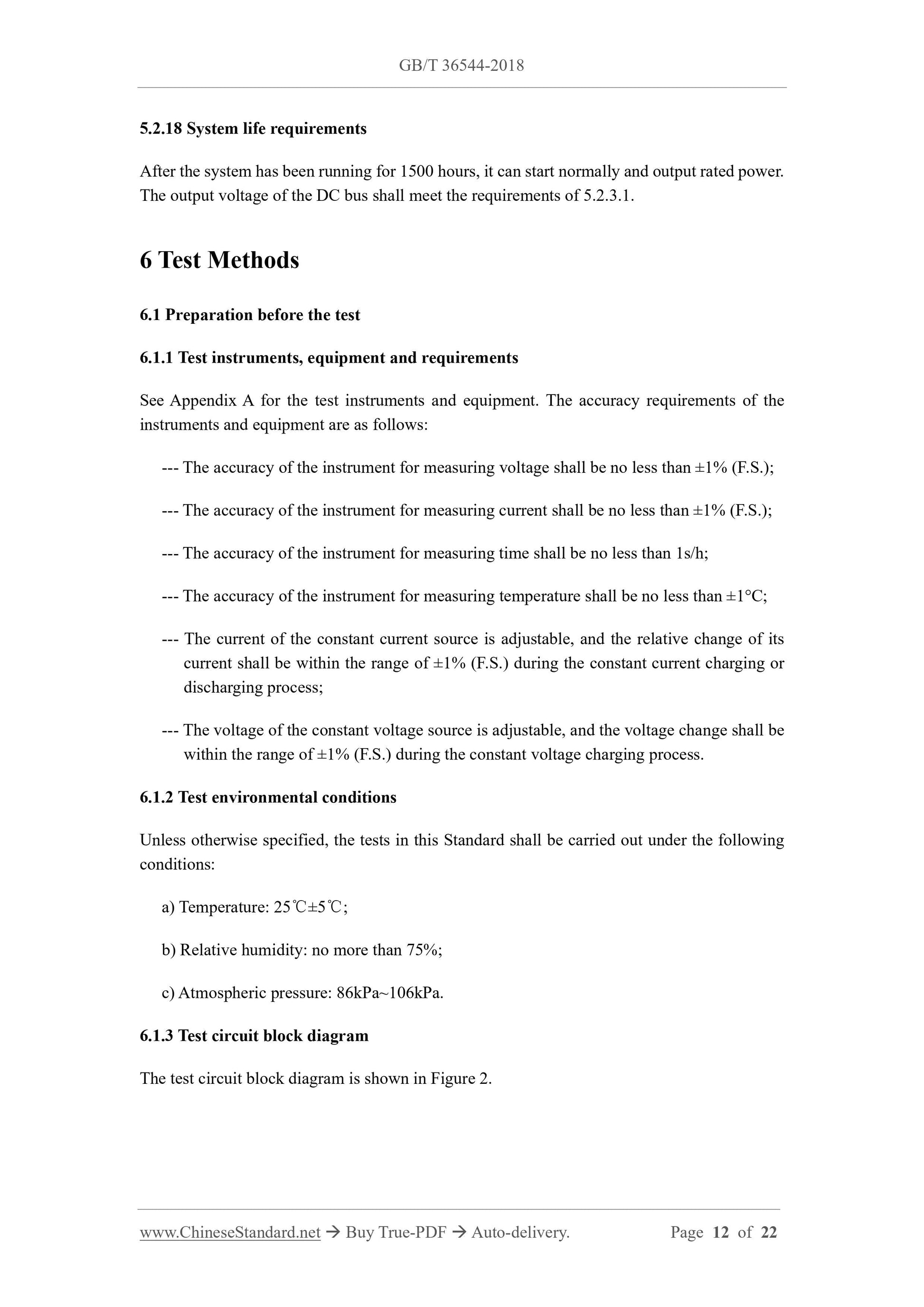
After the system has been running for 1500 hours, it can start normally and output rated power.
The output voltage of the DC bus shall meet the requirements of 5.2.3.1.
6 Test Methods
6.1 Preparation before the test
6.1.1 Test instruments, equipment and requirements
See Appendix A for the test instruments and equipment. The accuracy requirements of the
instruments and equipment are as follows:
--- The accuracy of the instrument for measuring voltage shall be no less than ±1% (F.S.);
--- The accuracy of the instrument for measuring current shall be no less than ±1% (F.S.);
--- The accuracy of the instrument for measuring time shall be no less than 1s/h;
--- The accuracy of the instrument for measuring temperature shall be no less than ±1°C;
--- The current of the constant current source is adjustable, and the relative change of its
current shall be within the range of ±1% (F.S.) during the constant current charging or
discharging process;
--- The voltage of the constant voltage source is adjustable, and the voltage change shall be
within the range of ±1% (F.S.) during the constant voltage charging process.
6.1.2 Test environmental conditions
Unless otherwise specified, the tests in this Standard shall be carried out under the following
conditions:
a) Temperature: 25℃±5℃;
b) Relative humidity: no more than 75%;
c) Atmospheric pressure: 86kPa~106kPa.
6.1.3 Test circuit block diagram
The test circuit block diagram is shown in Figure 2.
current for a duration of 500ms. During this period, the voltage value of the DC (power)
bus is measured (the test position is shown in Figure 2); and then resumes operation
under the rated current condition;
c) Repeat Procedure b) for 3 times with 2s interval each time.
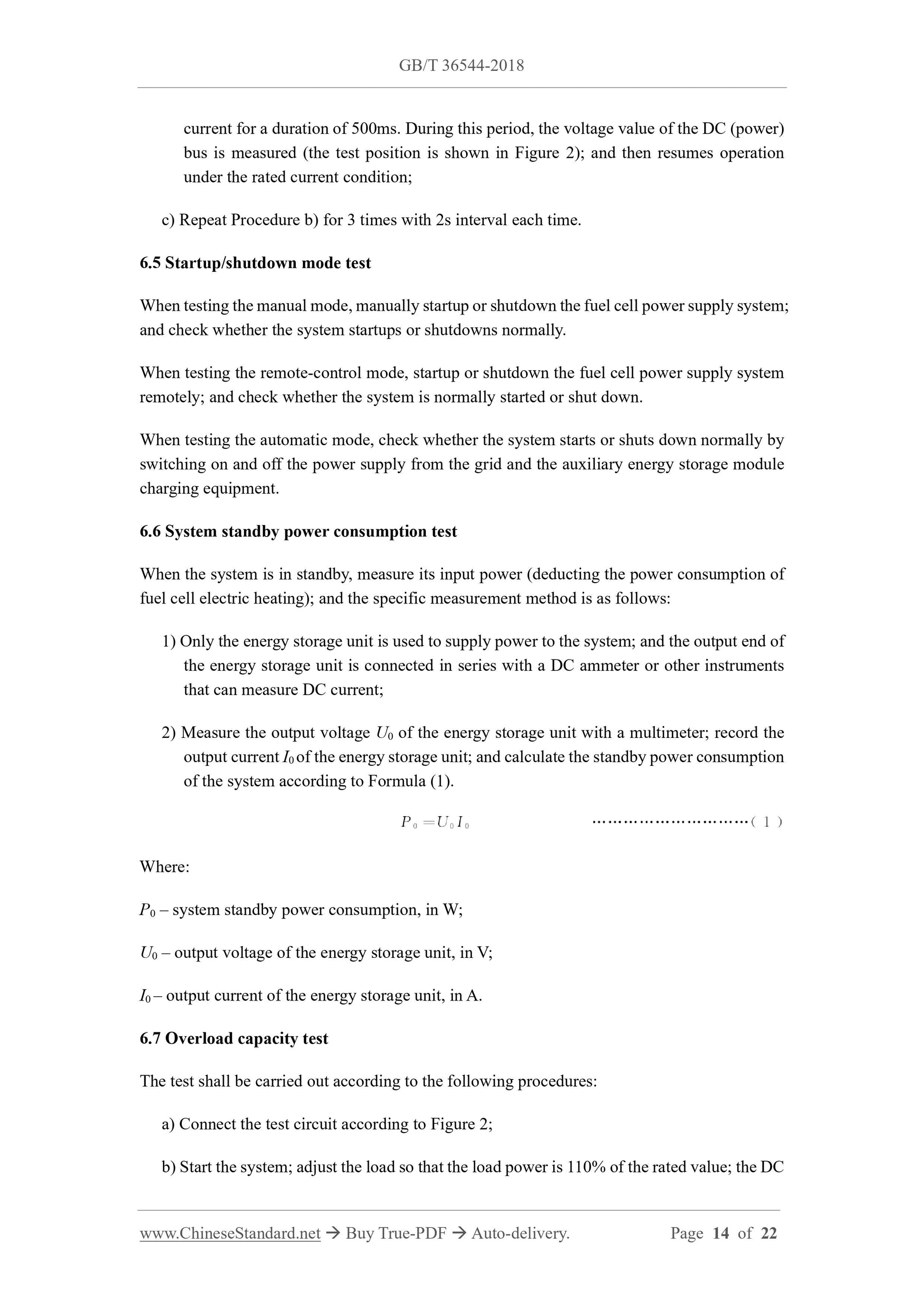
6.5 Startup/shutdown mode test
When testing the manual mode, manually startup or shutdown the fuel cell power supply system;
and check whether the system startups or shutdowns normally.
When testing the remote-control mode, startup or shutdown the fuel cell power supply system
remotely; and check whether the system is normally started or shut down.
When testing the automatic mode, check whether the system starts or shuts down normally by
switching on and off the power supply from the grid and the auxiliary energy storage module
charging equipment.
6.6 System standby power consumption test
When the system is in standby, measure its input power (deducting the power consumption of
fuel cell electric heating); and the specific measurement method is as follows:
1) Only the energy storage unit is used to supply power to the system; and the output end of
the energy storage unit is connected in series with a DC ammeter or other instruments
that can measure DC current;
2) Measure the output voltage U0 of the energy storage unit with a multimeter; record the
output current I0 of the energy storage unit; and calculate the standby power consumption
of the system according to Formula (1).
Where:
P0 – system standby power consumption, in W;
U0 – output voltage of the energy storage unit, in V;
I0 – output current of the energy storage unit, in A.
6.7 Overload capacity test
The test shall be carried out according to the following procedures:
a) Connect the test circuit according to Figure 2;
b) Start the system; adjust the load so that the load power is 110% of the rated value; the DC
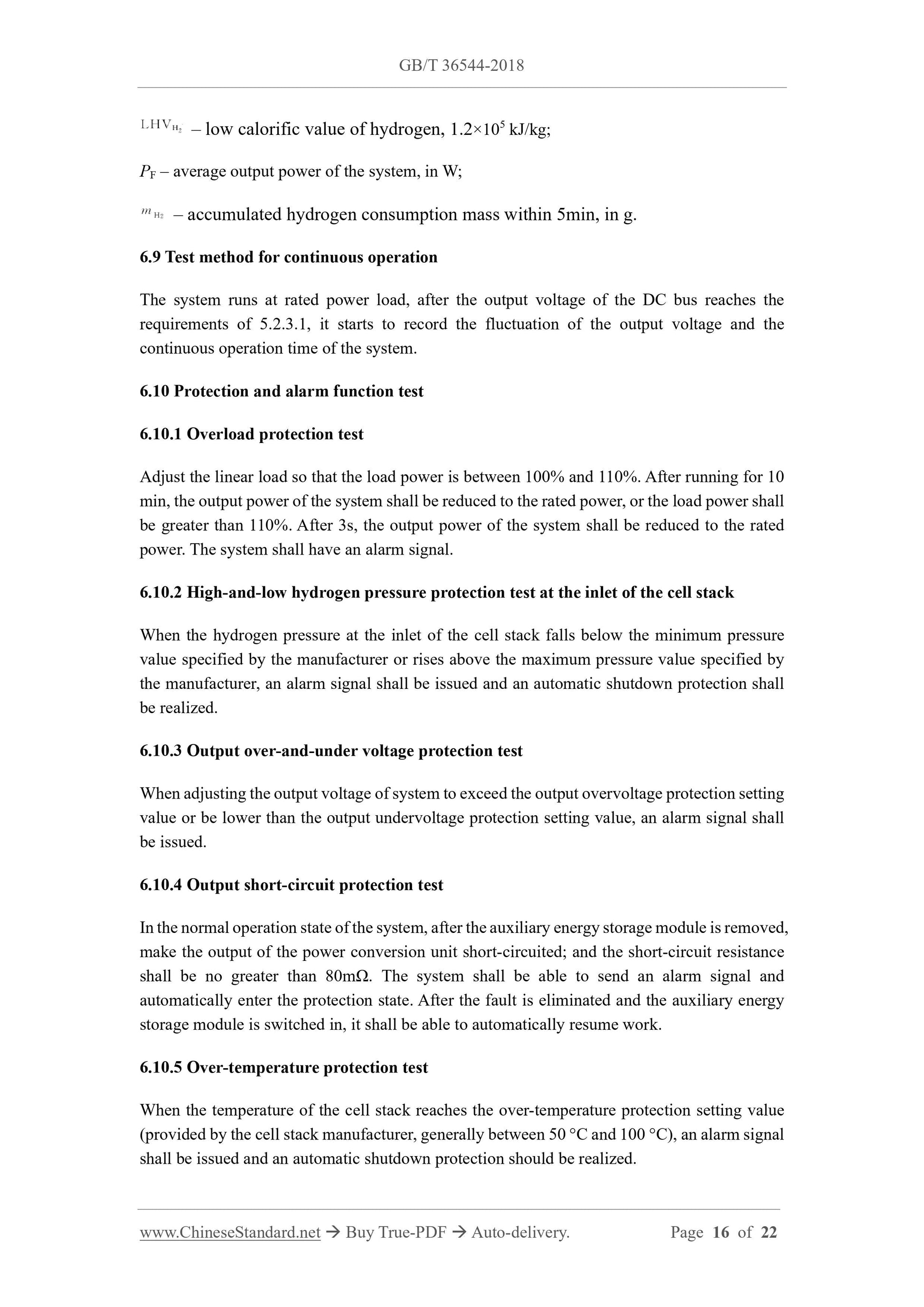
– low calorific value of hydrogen, 1.2×10⁵ kJ/kg;
PF – average output power of the system, in W;
– accumulated hydrogen consumption mass within 5min, in g.
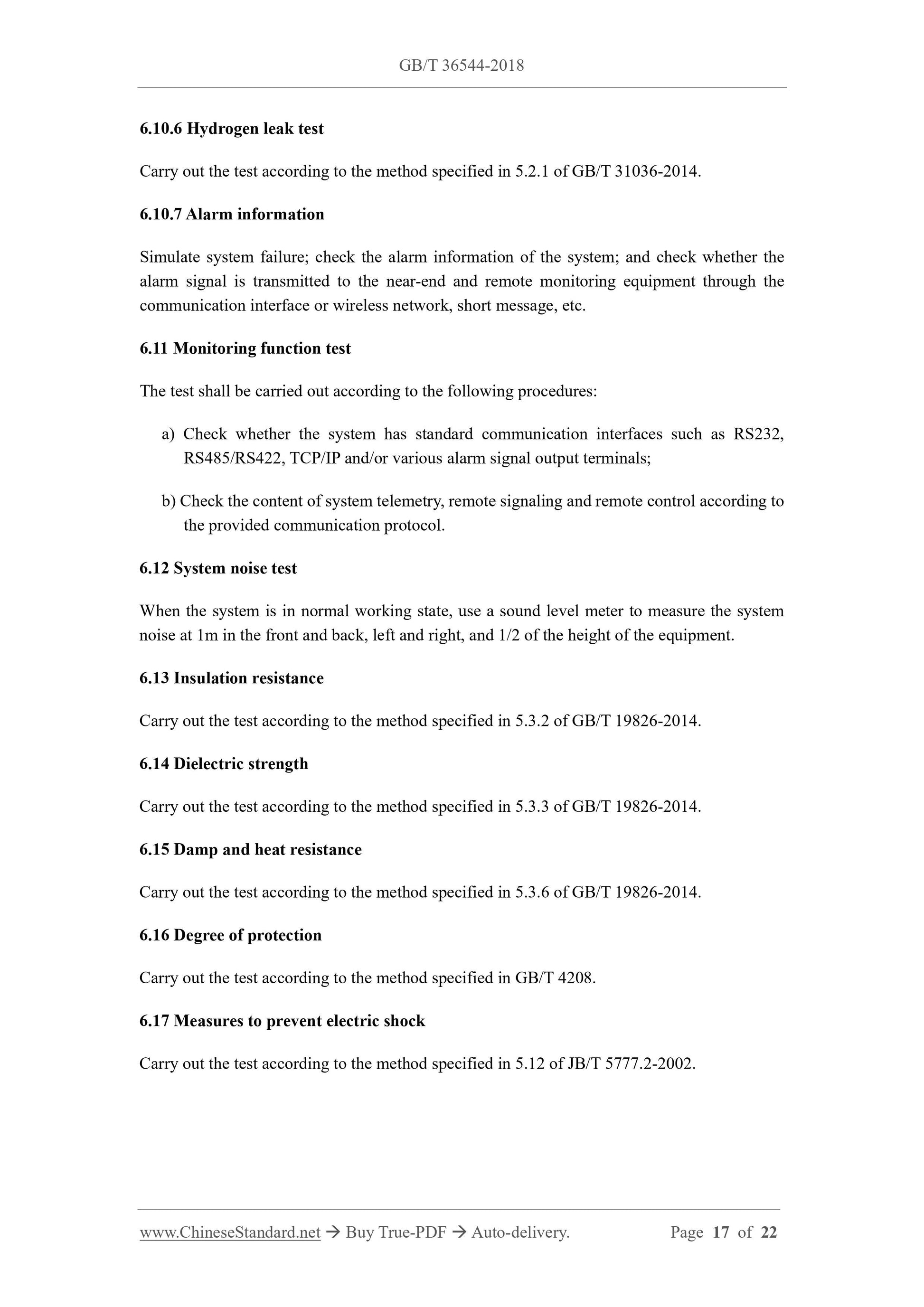
6.9 Test method for continuous operation
The system runs at rated power load, after the output voltage of the DC bus reaches the
requirements of 5.2.3.1, it starts to record the fluctuation of the output voltage and the
continuous op...
View full details