www.ChineseStandard.us -- Field Test Asia Pte. Ltd.
GB/T 34131-2023: Battery management system for electrical energy storage
Delivery: 9 seconds. Download (and Email) true-PDF + Invoice.
Get Quotation: Click
GB/T 34131-2023 (Self-service in 1-minute)
Newer / historical versions: GB/T 34131-2023Preview True-PDF
Scope
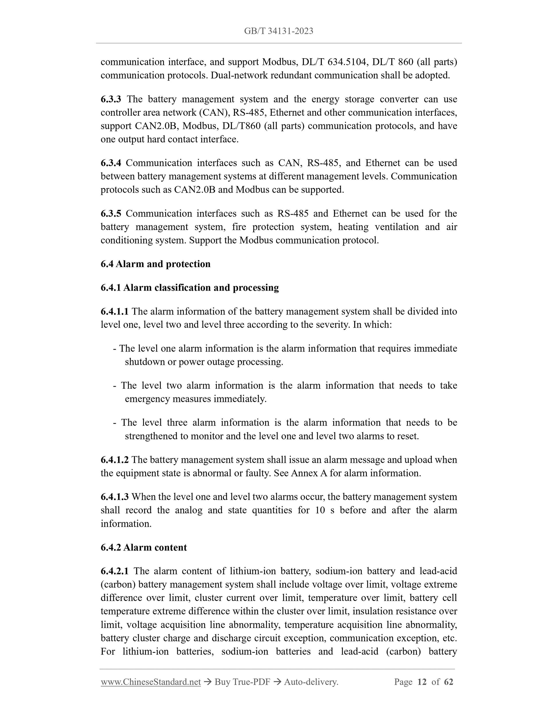
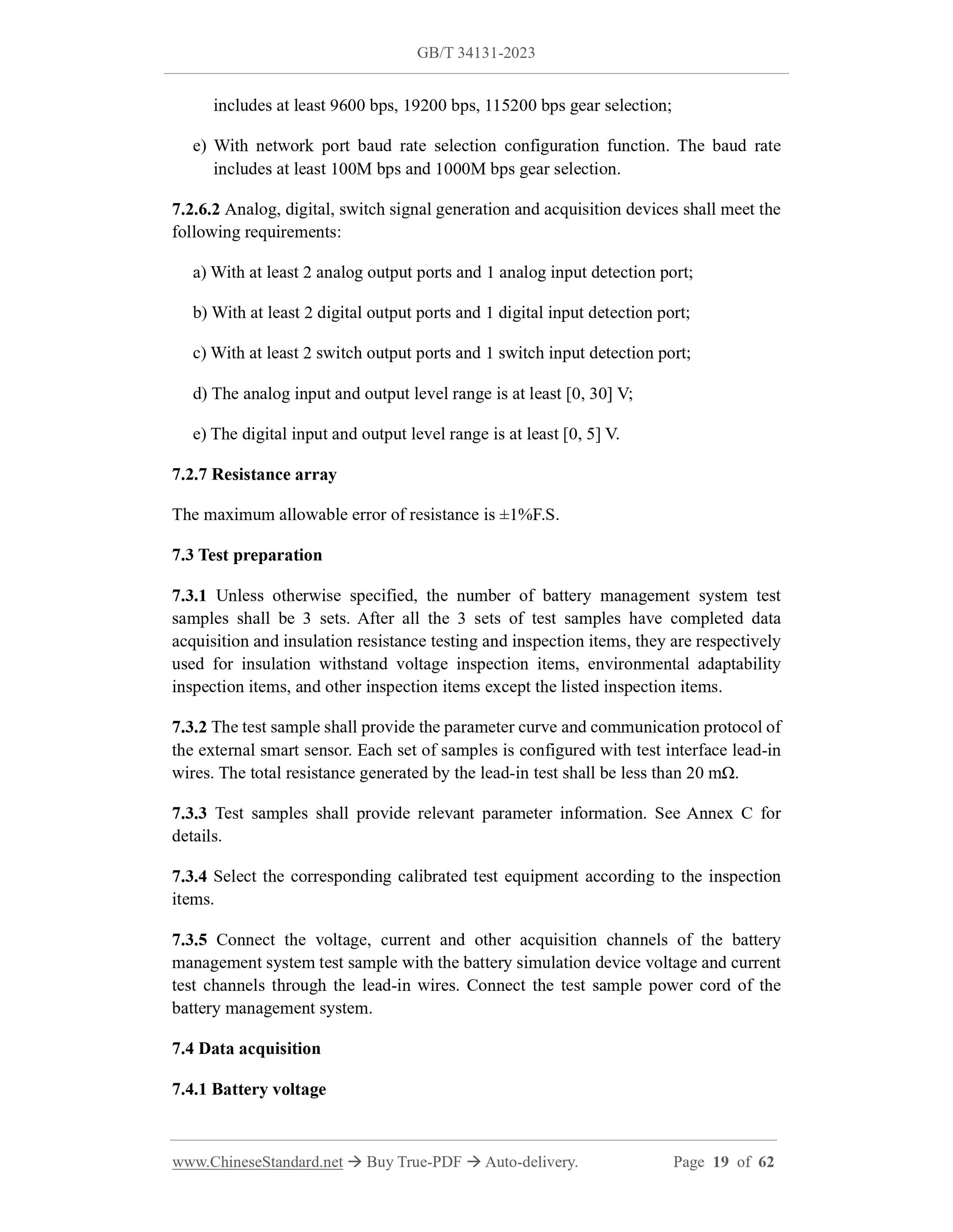
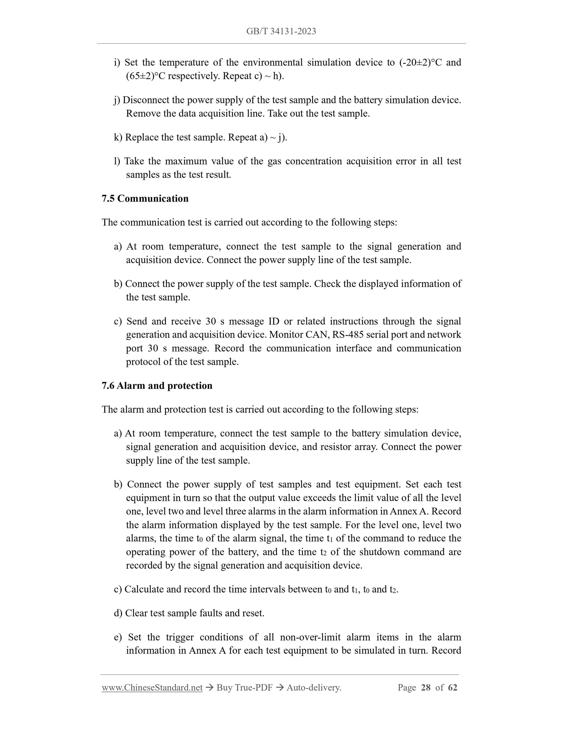
This document specifies the requirements for data acquisition, communication, alarm
and protection, control, energy state estimation, balance, insulation resistance detection,
insulation withstand voltage, electrical adaptability, and electromagnetic compatibility
of the battery management system for electric energy storage (referred to as "battery
management system"). It describes corresponding test methods. It stipulates
classification and coding, normal working environment, inspection rules, marks,
packaging, transportation and storage, etc.
This document is applicable to the design, manufacture, test, inspection, operation,
maintenance and overhaul of battery management systems for lithium-ion batteries,
sodium-ion batteries, lead-acid (carbon) batteries, flow batteries, and water
electrolysis/fuel cells for power storage. Other types of battery management systems
shall refer to this document for implementation.
Basic Data
| Standard ID | GB/T 34131-2023 (GB/T34131-2023) |
| Description (Translated English) | Battery management system for electrical energy storage |
| Sector / Industry | National Standard (Recommended) |
| Classification of Chinese Standard | F19 |
| Classification of International Standard | 27.180 |
| Word Count Estimation | 38,398 |
| Date of Issue | 2023-03-17 |
| Date of Implementation | 2023-10-01 |
| Older Standard (superseded by this standard) | GB/T 34131-2017 |
| Issuing agency(ies) | State Administration for Market Regulation, China National Standardization Administration |