1
/
of
8
www.ChineseStandard.us -- Field Test Asia Pte. Ltd.
GB/T 24825-2022 English PDF (GB/T24825-2022)
GB/T 24825-2022 English PDF (GB/T24825-2022)
Regular price
$230.00
Regular price
Sale price
$230.00
Unit price
/
per
Shipping calculated at checkout.
Couldn't load pickup availability
GB/T 24825-2022: DC or AC supplied electronic controlgear for LED modules - Performance specifications
Delivery: 9 seconds. Download (and Email) true-PDF + Invoice.Get Quotation: Click GB/T 24825-2022 (Self-service in 1-minute)
Newer / historical versions: GB/T 24825-2022
Preview True-PDF
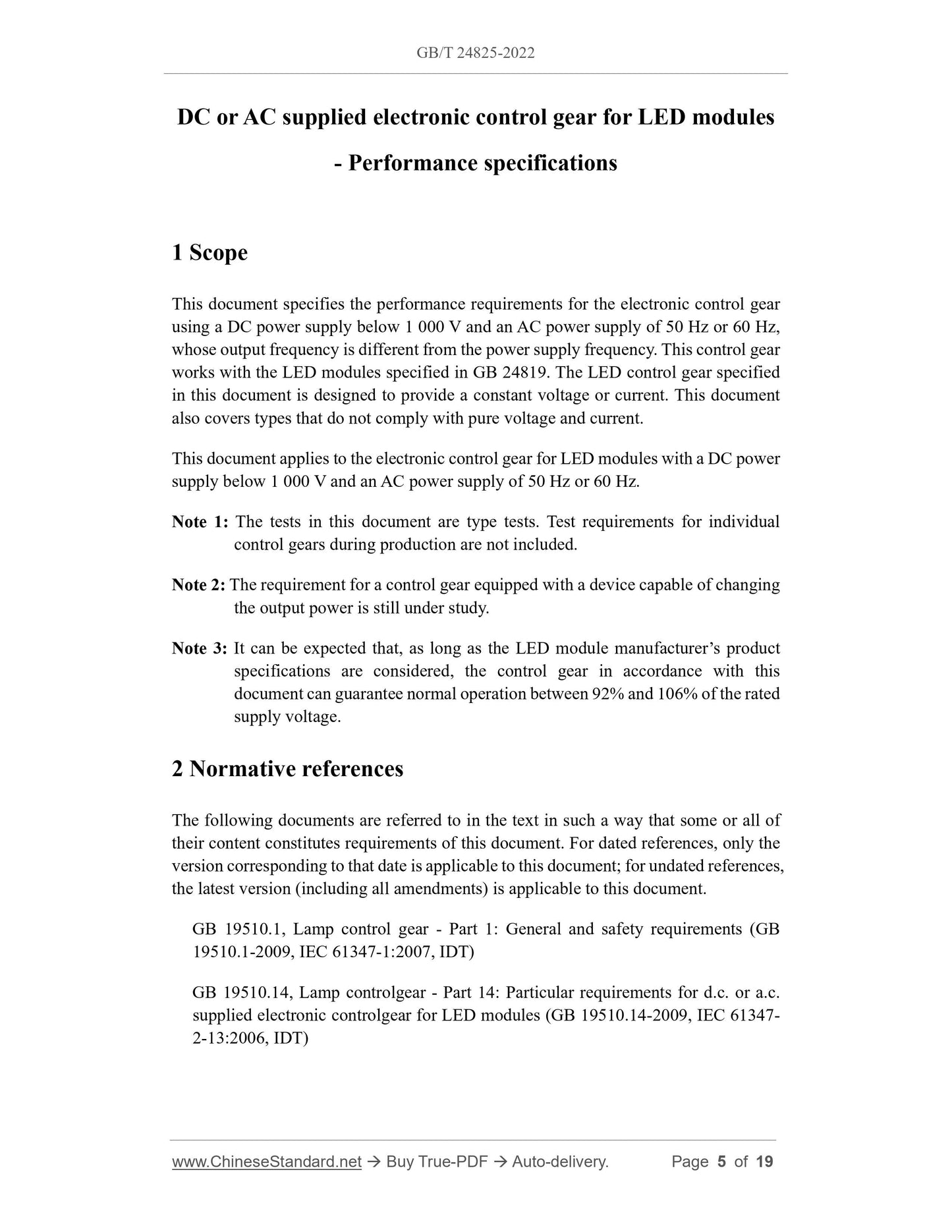
Scope
This document specifies the performance requirements for the electronic control gearusing a DC power supply below 1 000 V and an AC power supply of 50 Hz or 60 Hz,
whose output frequency is different from the power supply frequency. This control gear
works with the LED modules specified in GB 24819. The LED control gear specified
in this document is designed to provide a constant voltage or current. This document
also covers types that do not comply with pure voltage and current.
This document applies to the electronic control gear for LED modules with a DC power
supply below 1 000 V and an AC power supply of 50 Hz or 60 Hz.
Note 1: The tests in this document are type tests. Test requirements for individual
control gears during production are not included.
Note 2: The requirement for a control gear equipped with a device capable of changing
the output power is still under study.
Note 3: It can be expected that, as long as the LED module manufacturer’s product
specifications are considered, the control gear in accordance with this
document can guarantee normal operation between 92% and 106% of the rated
supply voltage.
Basic Data
| Standard ID | GB/T 24825-2022 (GB/T24825-2022) |
| Description (Translated English) | DC or AC supplied electronic controlgear for LED modules - Performance specifications |
| Sector / Industry | National Standard (Recommended) |
| Classification of Chinese Standard | K74 |
| Classification of International Standard | 29.140.99 |
| Word Count Estimation | 14,129 |
| Date of Issue | 2022-10-14 |
| Date of Implementation | 2023-05-01 |
| Older Standard (superseded by this standard) | GB/T 24825-2009 |
| Issuing agency(ies) | State Administration for Market Regulation, China National Standardization Administration |
Share