1
/
of
11
PayPal, credit cards. Download editable-PDF and invoice in 1 second!
GB/T 16508.5-2013 English PDF (GB/T16508.5-2013)
GB/T 16508.5-2013 English PDF (GB/T16508.5-2013)
Regular price
$140.00
Regular price
Sale price
$140.00
Unit price
/
per
Shipping calculated at checkout.
Couldn't load pickup availability
GB/T 16508.5-2013: Shell boilers – Part 5: Safety appurtenances and instruments
Delivery: 9 seconds. Download (and Email) true-PDF + Invoice.
Newer version: (Replacing this standard) GB/T 16508.5-2022
Get Quotation: Click GB/T 16508.5-2013 (Self-service in 1-minute)
Historical versions (Master-website): GB/T 16508.5-2022
Preview True-PDF (Reload/Scroll-down if blank)
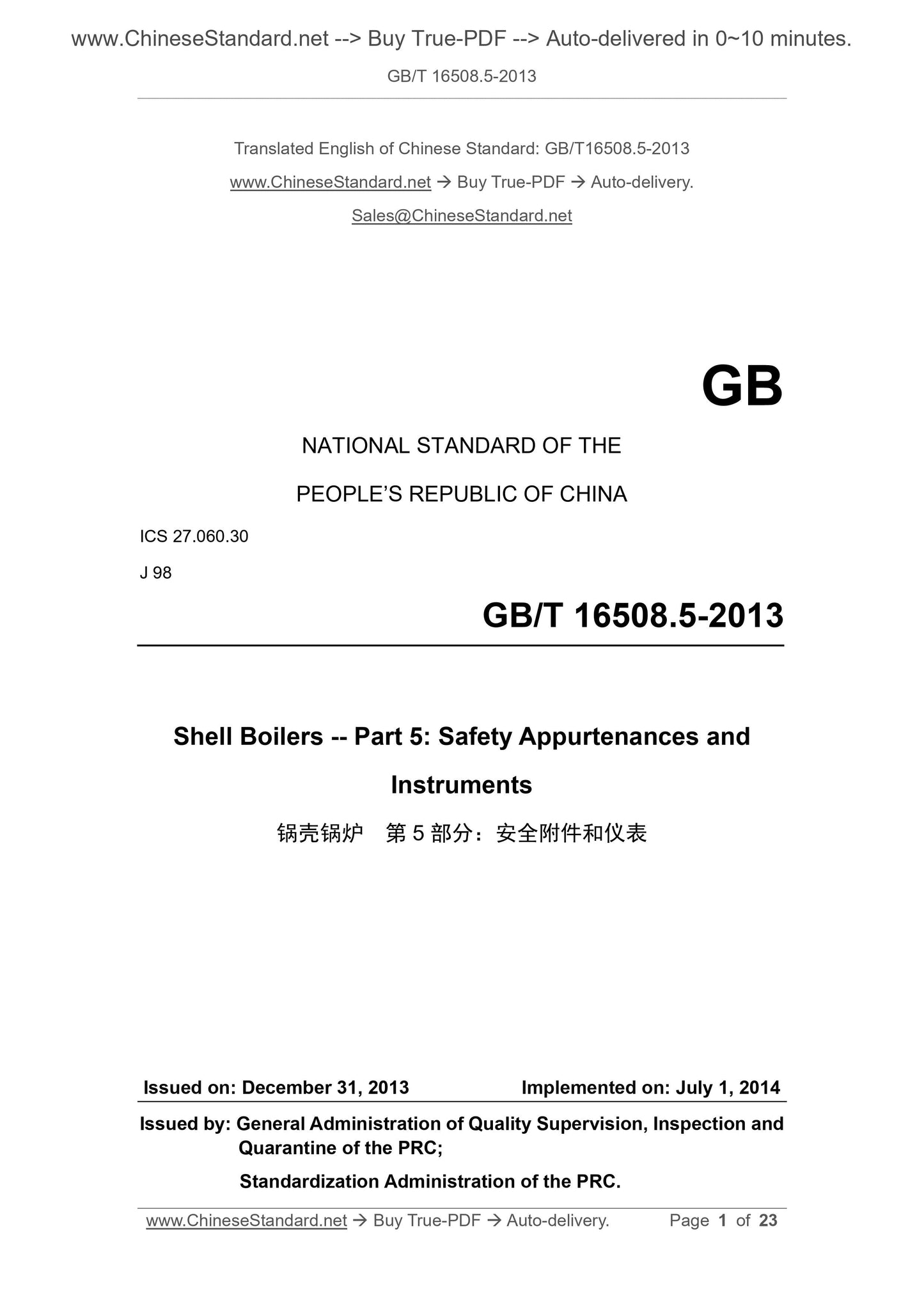
GB/T 16508.5-2013
NATIONAL STANDARD OF THE
PEOPLE’S REPUBLIC OF CHINA
ICS 27.060.30
J 98
Shell Boilers -- Part 5: Safety Appurtenances and
Instruments
ISSUED ON: DECEMBER 31, 2013
IMPLEMENTED ON: JULY 1, 2014
Issued by: General Administration of Quality Supervision, Inspection and
Quarantine of the PRC;
Standardization Administration of the PRC.
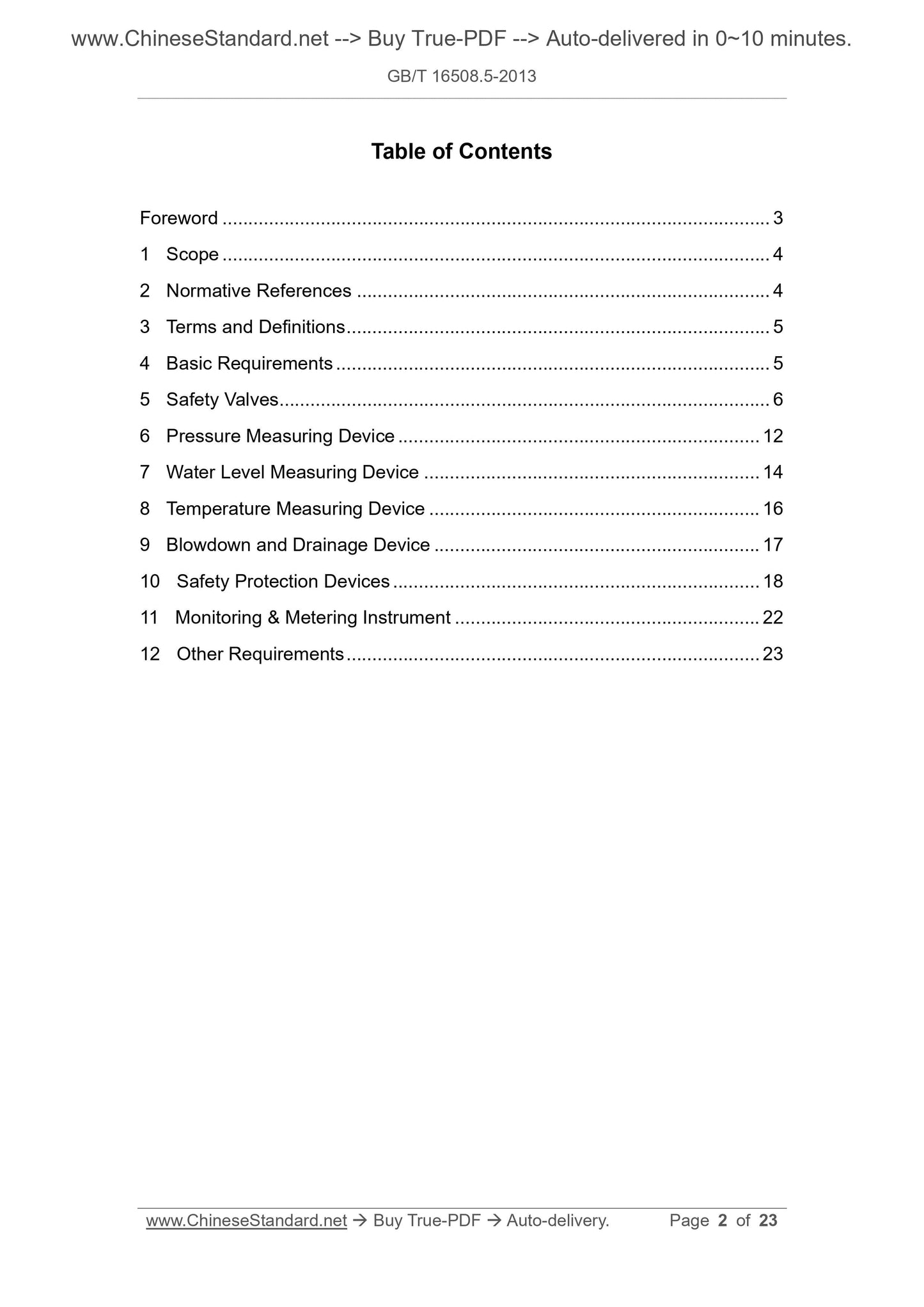
Table of Contents
Foreword ... 3
1 Scope ... 4
2 Normative References ... 4
3 Terms and Definitions ... 5
4 Basic Requirements ... 5
5 Safety Valves ... 6
6 Pressure Measuring Device ... 12
7 Water Level Measuring Device ... 14
8 Temperature Measuring Device ... 16
9 Blowdown and Drainage Device ... 17
10 Safety Protection Devices ... 18
11 Monitoring and Metering Instrument ... 22
12 Other Requirements ... 23
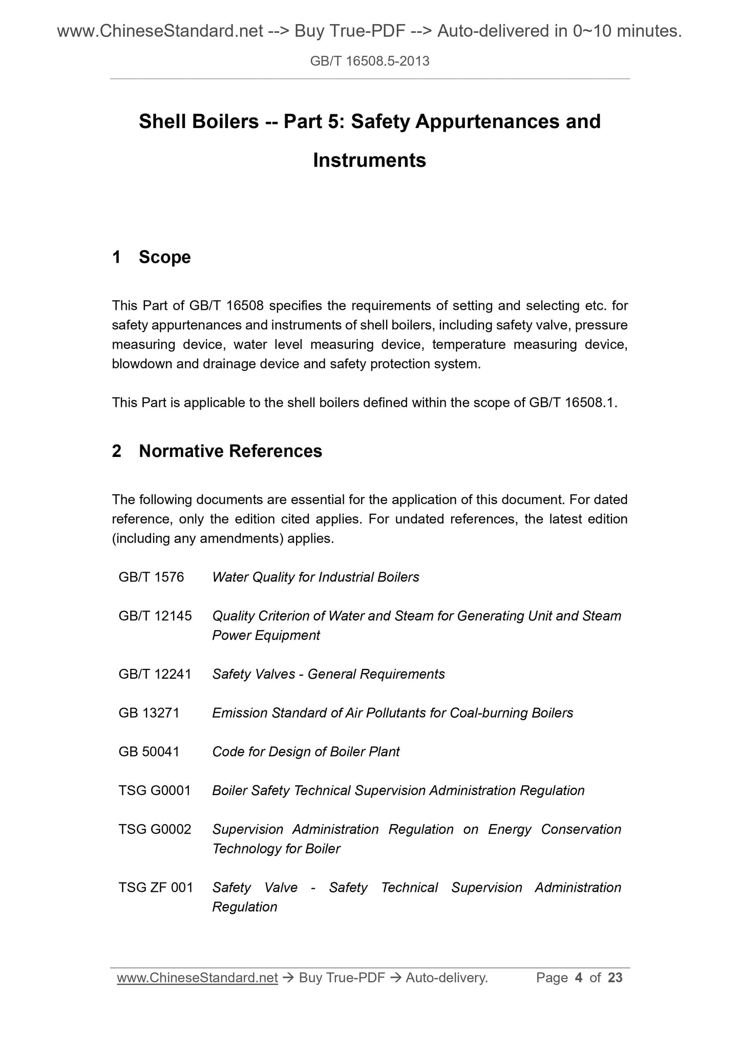
Shell Boilers -- Part 5: Safety Appurtenances and
Instruments
1 Scope
This Part of GB/T 16508 specifies the requirements of setting and selecting etc. for
safety appurtenances and instruments of shell boilers, including safety valve, pressure
measuring device, water level measuring device, temperature measuring device,
blowdown and drainage device and safety protection system.
This Part is applicable to the shell boilers defined within the scope of GB/T 16508.1.
2 Normative References
The following documents are essential for the application of this document. For dated
reference, only the edition cited applies. For undated references, the latest edition
(including any amendments) applies.
GB/T 1576 Water Quality for Industrial Boilers
GB/T 12145 Quality Criterion of Water and Steam for Generating Unit and Steam
Power Equipment
GB/T 12241 Safety Valves - General Requirements
GB 13271 Emission Standard of Air Pollutants for Coal-burning Boilers
GB 50041 Code for Design of Boiler Plant
TSG G0001 Boiler Safety Technical Supervision Administration Regulation
TSG G0002 Supervision Administration Regulation on Energy Conservation
Technology for Boiler
TSG ZF 001 Safety Valve - Safety Technical Supervision Administration
Regulation
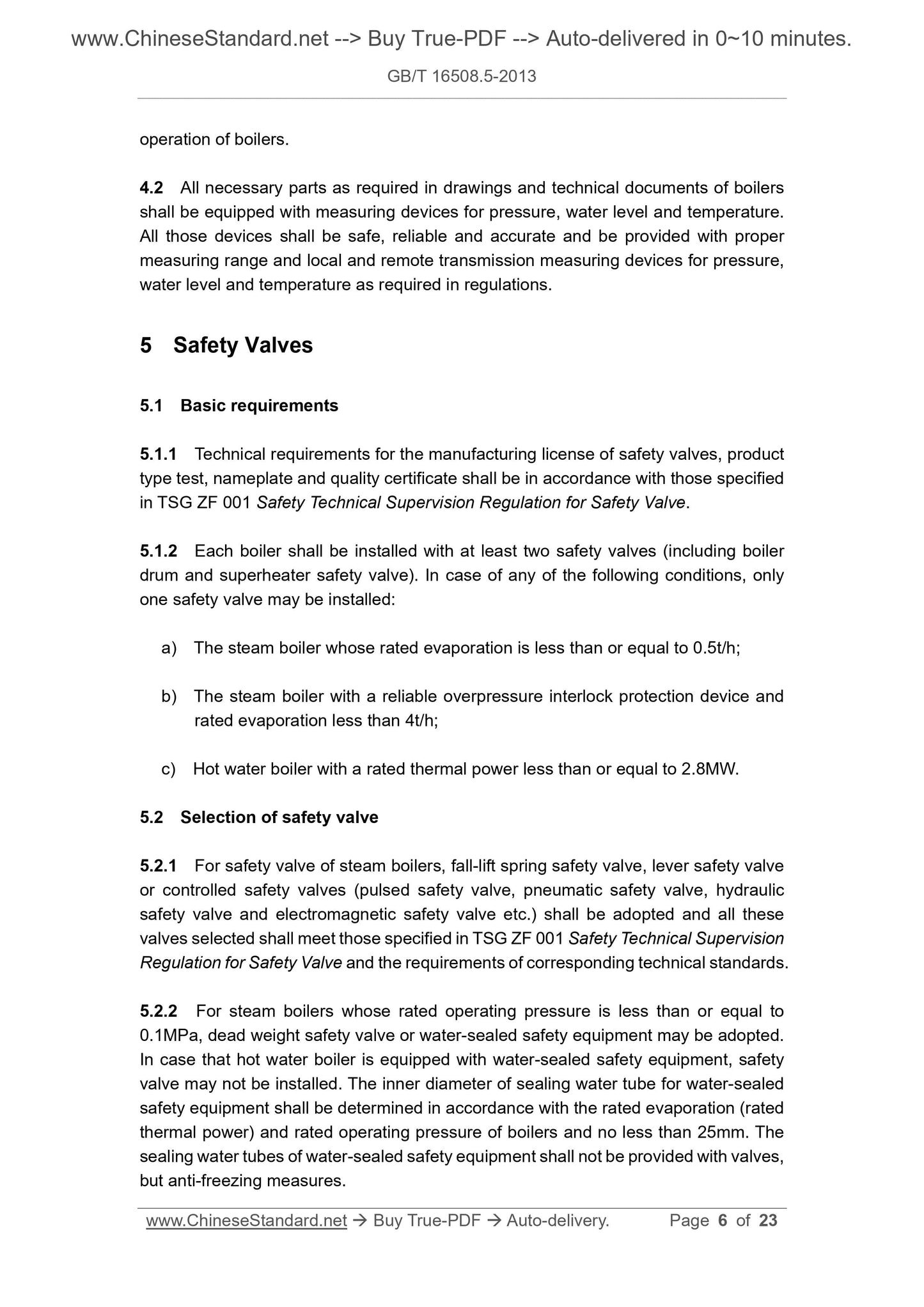
operation of boilers.
4.2 All necessary parts as required in drawings and technical documents of boilers
shall be equipped with measuring devices for pressure, water level and temperature.
All those devices shall be safe, reliable and accurate and be provided with proper
measuring range and local and remote transmission measuring devices for pressure,
water level and temperature as required in regulations.
5 Safety Valves
5.1 Basic requirements
5.1.1 Technical requirements for the manufacturing license of safety valves, product
type test, nameplate and quality certificate shall be in accordance with those specified
in TSG ZF 001 Safety Technical Supervision Regulation for Safety Valve.
5.1.2 Each boiler shall be installed with at least two safety valves (including boiler
drum and superheater safety valve). In case of any of the following conditions, only
one safety valve may be installed:
a) The steam boiler whose rated evaporation is less than or equal to 0.5t/h;
b) The steam boiler with a reliable overpressure interlock protection device and
rated evaporation less than 4t/h;
c) Hot water boiler with a rated thermal power less than or equal to 2.8MW.
5.2 Selection of safety valve
5.2.1 For safety valve of steam boilers, fall-lift spring safety valve, lever safety valve
or controlled safety valves (pulsed safety valve, pneumatic safety valve, hydraulic
safety valve and electromagnetic safety valve etc.) shall be adopted and all these
valves selected shall meet those specified in TSG ZF 001 Safety Technical Supervision
Regulation for Safety Valve and the requirements of corresponding technical standards.
5.2.2 For steam boilers whose rated operating pressure is less than or equal to
0.1MPa, dead weight safety valve or water-sealed safety equipment may be adopted.
In case that hot water boiler is equipped with water-sealed safety equipment, safety
valve may not be installed. The inner diameter of sealing water tube for water-sealed
safety equipment shall be determined in accordance with the rated evaporation (rated
thermal power) and rated operating pressure of boilers and no less than 25mm. The
sealing water tubes of water-sealed safety equipment shall not be provided with valves,
but anti-freezing measures.
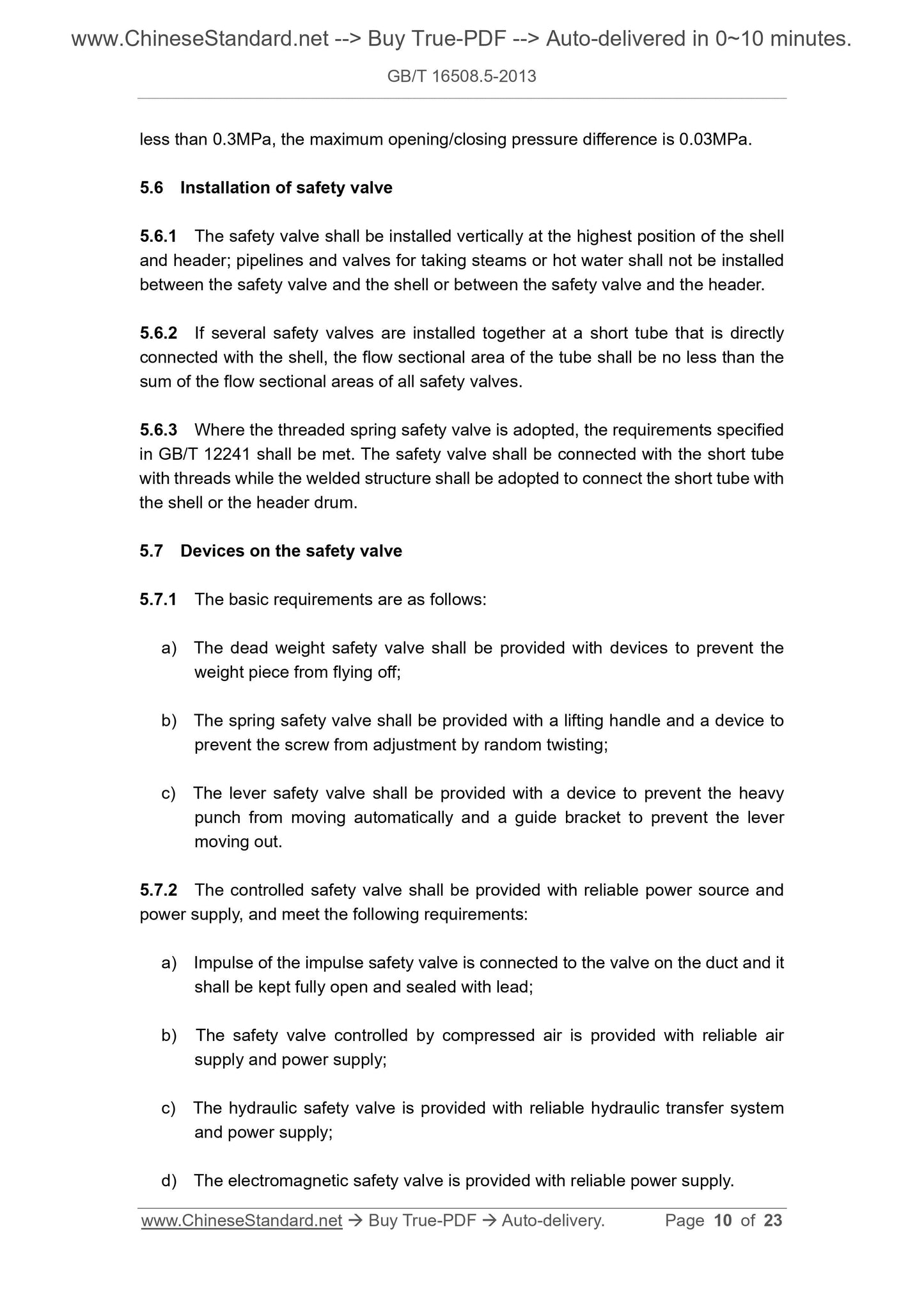
less than 0.3MPa, the maximum opening/closing pressure difference is 0.03MPa.
5.6 Installation of safety valve
5.6.1 The safety valve shall be installed vertically at the highest position of the shell
and header; pipelines and valves for taking steams or hot water shall not be installed
between the safety valve and the shell or between the safety valve and the header.
5.6.2 If several safety valves are installed together at a short tube that is directly
connected with the shell, the flow sectional area of the tube shall be no less than the
sum of the flow sectional areas of all safety valves.
5.6.3 Where the threaded spring safety valve is adopted, the requirements specified
in GB/T 12241 shall be met. The safety valve shall be connected with the short tube
with threads while the welded structure shall be adopted to connect the short tube with
the shell or the header drum.
5.7 Devices on the safety valve
5.7.1 The basic requirements are as follows:
a) The dead weight safety valve shall be provided with devices to prevent the
weight piece from flying off;
b) The spring safety valve shall be provided with a lifting handle and a device to
prevent the screw from adjustment by random twisting;
c) The lever safety valve shall be provided with a device to prevent the heavy
punch from moving automatically and a guide bracket to prevent the lever
moving out.
5.7.2 The controlled safety valve shall be provided with reliable power source and
power supply, and meet the following requirements:
a) Impulse of the impulse safety valve is connected to the valve on the duct and it
shall be kept fully open and sealed with lead;
b) The safety valve controlled by compressed air is provided with reliable air
supply and power supply;
c) The hydraulic safety valve is provided with reliable hydraulic transfer system
and power supply;
d) The electromagnetic safety valve is provided with reliable power supply.
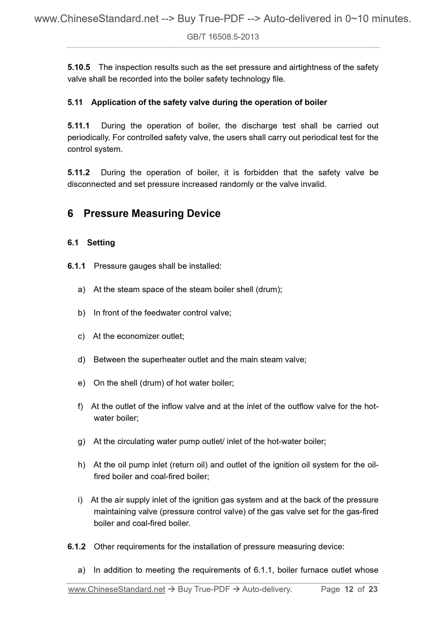
5.10.5 The inspection results such as the set pressure and airtightness of the safety
valve shall be recorded into the boiler safety technology file.
5.11 Application of the safety valve during the operation of boiler
5.11.1 During the operation of boiler, the discharge test shall be carried out
periodically. For controlled safety valve, the users shall carry out periodical test for the
control system.
5.11.2 During the operation of boiler, it is forbidden that the safety valve be
disconnected and set pressure increased randomly or the valve invalid.
6 Pressure Measuring Device
6.1 Setting
6.1.1 Pressure gauges shall be installed:
a) At the steam space of the steam boiler shell (drum);
b) In front of the feedwater control valve;
c) At the economizer outlet;
d) Between the superheater outlet and the main steam valve;
e) On the shell (drum) of hot water boiler;
f) At the outlet of the inflow valve and at the inlet of the outflow valve for the hot-
water boiler;
g) At the circulating water pump outlet/ inlet of the hot-water boiler;
h) At the oil pump inlet (return oil) and outlet of the ignition oil system for the oil-
fired boiler and coal-fired boiler;
i) At the air supply inlet of the ignition gas system and at the back of the pressure
maintaining valve (pressure control valve) of the gas valve set for the gas-fired
boiler and coal-fired boiler.
6.1.2 Other requirements for the installation of pressure measuring device:
a) In addition to meeting the requirements of 6.1.1, boiler furnace outlet whose
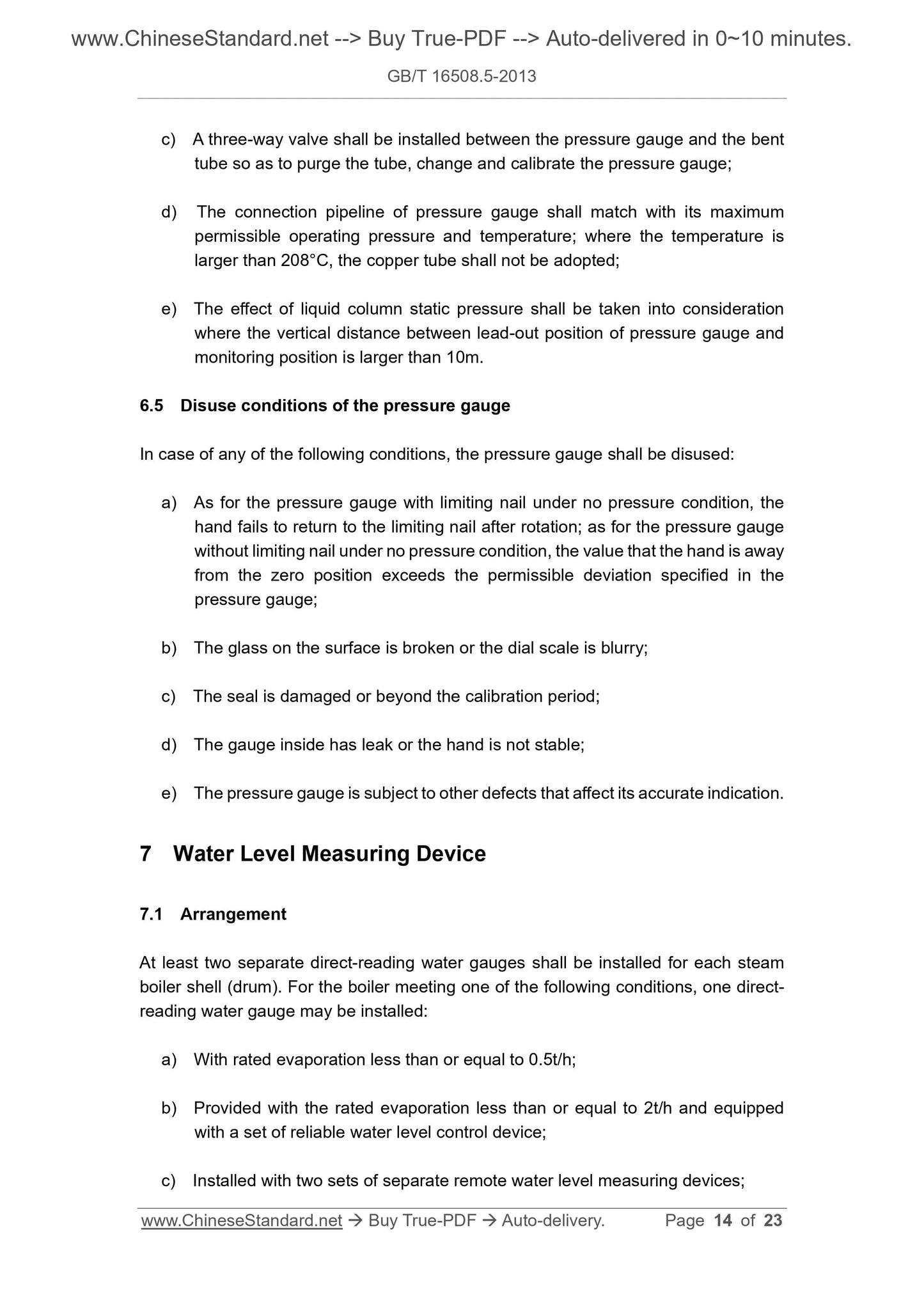
c) A three-way valve shall be installed between the pressure gauge and the bent
tube so as to purge the tube, change and calibrate the pressure gauge;
d) The connection pipeline of pressure gauge shall match with its maximum
permissible operating pressure and temperature; where the temperature is
larger than 208°C, the copper tube shall not be adopted;
e) The effect of liquid column static pressure shall be taken into consideration
where the vertical distance between lead-out position of pressure gauge and
monitoring position is larger than 10m.
6.5 Disuse conditions of the pressure gauge
In case of any of the following conditions, the pressure gauge shall be disused:
a) As for the pressure gauge with limiting nail under no pressure condition, the
hand fails to return to the limiting nail after rotation; as for the pressure gauge
without limiting nail under no pressure condition, the value that the hand is away
from the zero position exceeds the permissible deviation specified in the
pressure gauge;
b) The glass on the surface is broken or the dial scale is blurry;
c) The seal is damaged or beyond the calibration period;
d) The gauge inside has leak or the hand is not stable;
e) The pressure gauge is subject to other defects that affect its accurate indication.
7 Water Level Measuring Device
7.1 Arrangement
At least two separate direct-reading water gauges shall be installed for each steam
boiler shell (drum). For the boiler meeting one of the following conditions, one direct-
reading water gauge may be installed:
a) With rated evaporation less than or equal to 0.5t/h;
b) Provided with the rated evaporation less than or equal to 2t/h and equipped
with a set of reliable water level control device;
c) Installed with two sets of separate remote water level measuring devices;
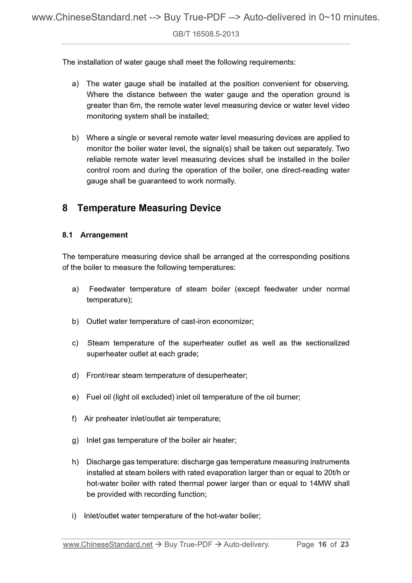
The installation of water gauge shall meet the following requirements:
a) The water gauge shall be installed at the position convenient for observing.
Where the distance between the water gauge and the operation ground is
greater than 6m, the remote water level measuring device or water level video
monitoring system shall be installed;
b) Where a single or several remote water level measuring devices are applied to
monitor the boiler water level, the signal(s) shall be taken out separately. Two
reliable remote water level measuring devices shall be installed in the boiler
control room and during the operation of the boiler, one direct-reading water
gauge shall be guaranteed to work normally.
8 Temperature Measuring Device
8.1 Arrangement
The temperature measuring device shall be arranged at the corresponding positions
of the boiler to measure the following temperatures:
a) Feedwater temperature of steam boiler (except feedwater under normal
temperature);
b) Outlet water temperature of cast-iron economizer;
c) Steam temperature of the superheater outlet as well as the sectionalized
superheater outlet at each grade;
d) Front/rear steam temperature of desuperheater;
e) Fuel oil (light oil excluded) inlet oil temperature of the oil burner;
f) Air preheater inlet/outlet air temperature;
g) Inlet gas temperature of the boiler air heater;
h) Discharge gas temperature: discharge gas temperature measuring instruments
installed at steam boilers with rated evaporation larger than or equal to 20t/h or
hot-water boiler with rated thermal power larger than or equal to 14MW shall
be provided with recording function;
i) Inlet/outlet water temperature of the hot-water boiler;
on it;
f) Where one main blowdown tube is jointly used for several boilers, simultaneous
blowdown from over two boilers shall be avoided;
g) Threaded connection should not be adopted for the boiler blowdown valve and
blowdown tube.
9.2 Outlet tube of hot-water boiler is generally arranged at the topmost of boiler; and
gas extractor shall be arranged at the topmost of outlet tube in front of outlet valve.
Exhaust valve with nominal diameter greater than or equal to 20mm shall be arranged
at the topmost of each loop and boiler shell (drum) or outlet tube. Exhaust tube at the
topmost of each boiler loop should be centrally arranged.
9.3 Drain tube shall be arranged on the topmost of the boiler shell (drum) or outlet
tube, its inner diameter shall be determined according to the rated thermal power of
the boiler, and it shall be no less than 25mm. Relief valve shall be arranged on the
drain tube and where the boiler is under normal operation, the relief valve is closed.
For boiler arranged with relief valve, its boiler shell (drum) or outlet tube may not be
arranged with exhaust valve.
9.4 Blowdown valve or drain valve shall be arranged in boiler shell (drum) as well as
the lowest position of header under each circulation loop.
10 Safety Protection Devices
10.1 Basic requirements
10.1.1 Steam boiler shall be installed with high/low water level alarm and low water
level interlock protection device (higher/low water level alarm signal shall be
discriminated) and protection device shall operate at lowest safe water level at latest.
10.1.2 As for the boiler with rated evaporation larger than or equal to 6t/h, the steam
overpressure alarm device and interlock protection device shall be installed; and the
operation set value of the overpressure interlock protection device shall be less than
the lower set pressure of the safety valve.
10.1.3 Boiler installed in the multistory or high-rise building shall be equipped with
overpressure (overheat) interlock protection device.
10.1.4 Gas-fired boiler shall be provided with gas leakage monitoring and alarm
device.
10.1.5 Superheat alarm device and interlock protection device shall be installed for
hot-water boiler within the following range:
a) Rated operating pressure less than 3.8MPa, nominal outlet temperature less
than 120°C and rated thermal power larger than or equal to 7MW;
b) Rated operating pressure less than 3.8MPa and nominal outlet temperature
larger than or equal to 120°C.
10.1.6 For grate firing hot-water boiler, devices which can automatically stop air blast
and induction shall be arranged where pressure of the boiler reduces to the degree
that vaporization hap...
Share
