Skip to product information
1 of 10

PayPal, credit cards. Download editable-PDF and invoice in 1 second!

GB/T 12243-2021 English PDF (GB/T12243-2021)

GB/T 12243-2021 English PDF (GB/T12243-2021)

Regular price $365.00 USD
Regular price Sale price $365.00 USD
Sale Sold out
Shipping calculated at checkout.
Delivery: 3 seconds. Download true-PDF + Invoice.
Get Quotation: Click GB/T 12243-2021 (Self-service in 1-minute)
Historical versions (Master-website): GB/T 12243-2021
Preview True-PDF (Reload/Scroll-down if blank)

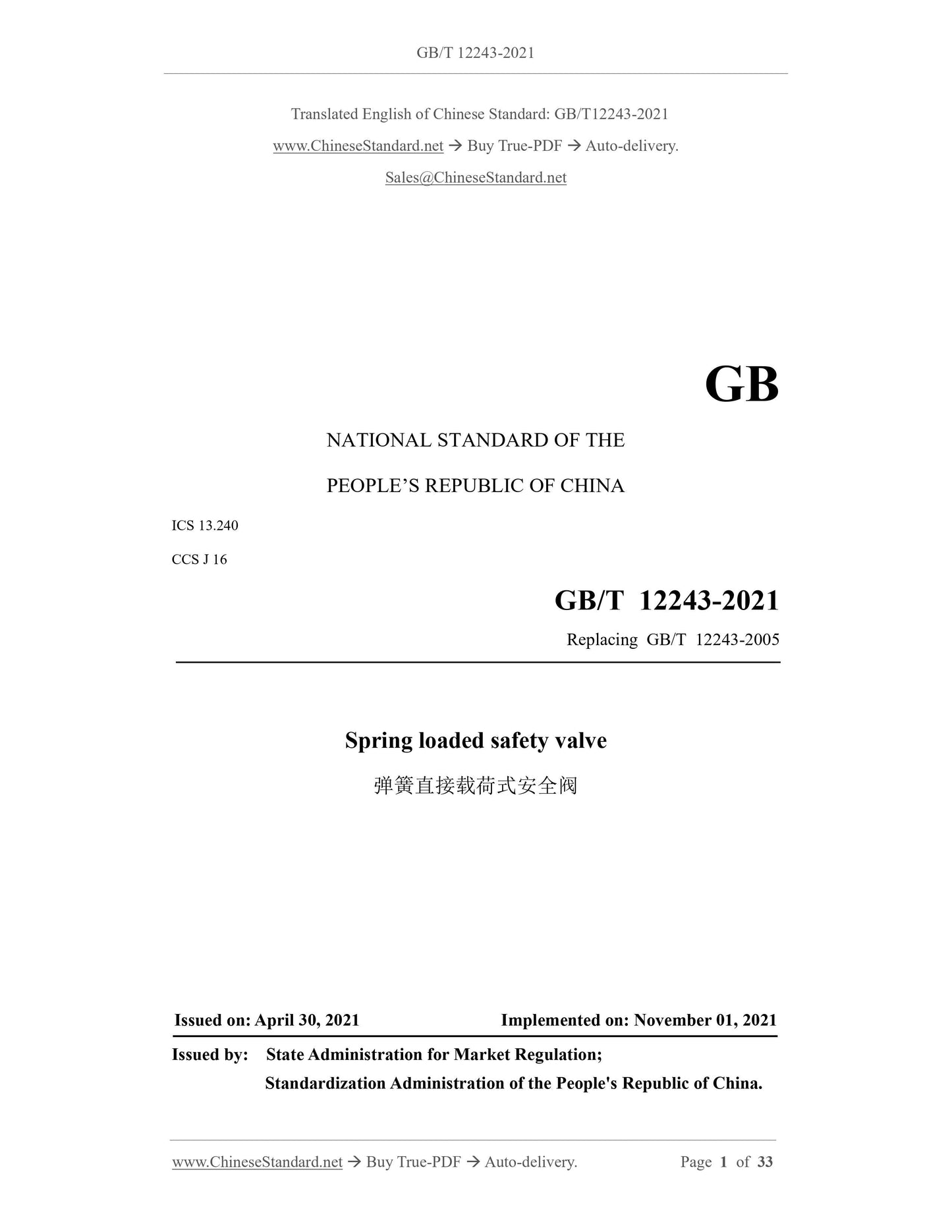
GB/T 12243-2021: Spring loaded safety valves
GB/T 12243-2021
Spring loaded safety valves
ICS 13.240
CCSJ16
National Standards of People's Republic of China
Replace GB/T 12243-2005
Spring direct load safety valve
Released on 2021-04-30
2021-11-01 implementation
State Administration of Market Supervision and Administration
Issued by the National Standardization Management Committee
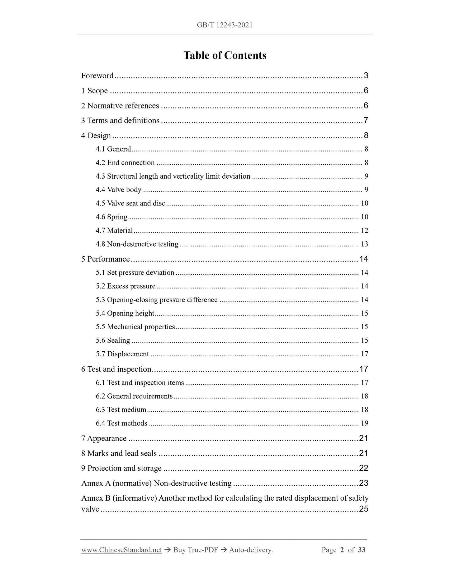
Table of contents
Foreword Ⅲ
1 Scope 1
2 Normative references 1
3 Terms and definitions 1
4 Design 2
4.1 General 2
4.2 End connection 2
4.3 Limit deviation of structure length and perpendicularity 2
4.4 Valve body 3
4.5 Valve seat and disc 3
4.6 Spring 3
4.7 Material 5
4.8 Non-destructive testing 5
5 Performance 5
5.1 Setting pressure deviation 5
5.2 Excessive pressure 6
5.3 Opening and closing pressure difference 6
5.4 Opening height 7
5.5 Mechanical characteristics 7
5.6 Tightness 7
5.7 Displacement 8
6 Test and inspection 8
6.1 Test and inspection items 8
6.2 General requirements 9
6.3 Test medium 9
6.4 Test method 9
7 Appearance 11
8 Marks and seals 11
9 Protection, storage and transportation 12
Appendix A (normative) Non-destructive testing 13
Appendix B (Informative) Another method for calculating the rated displacement of safety valves 15
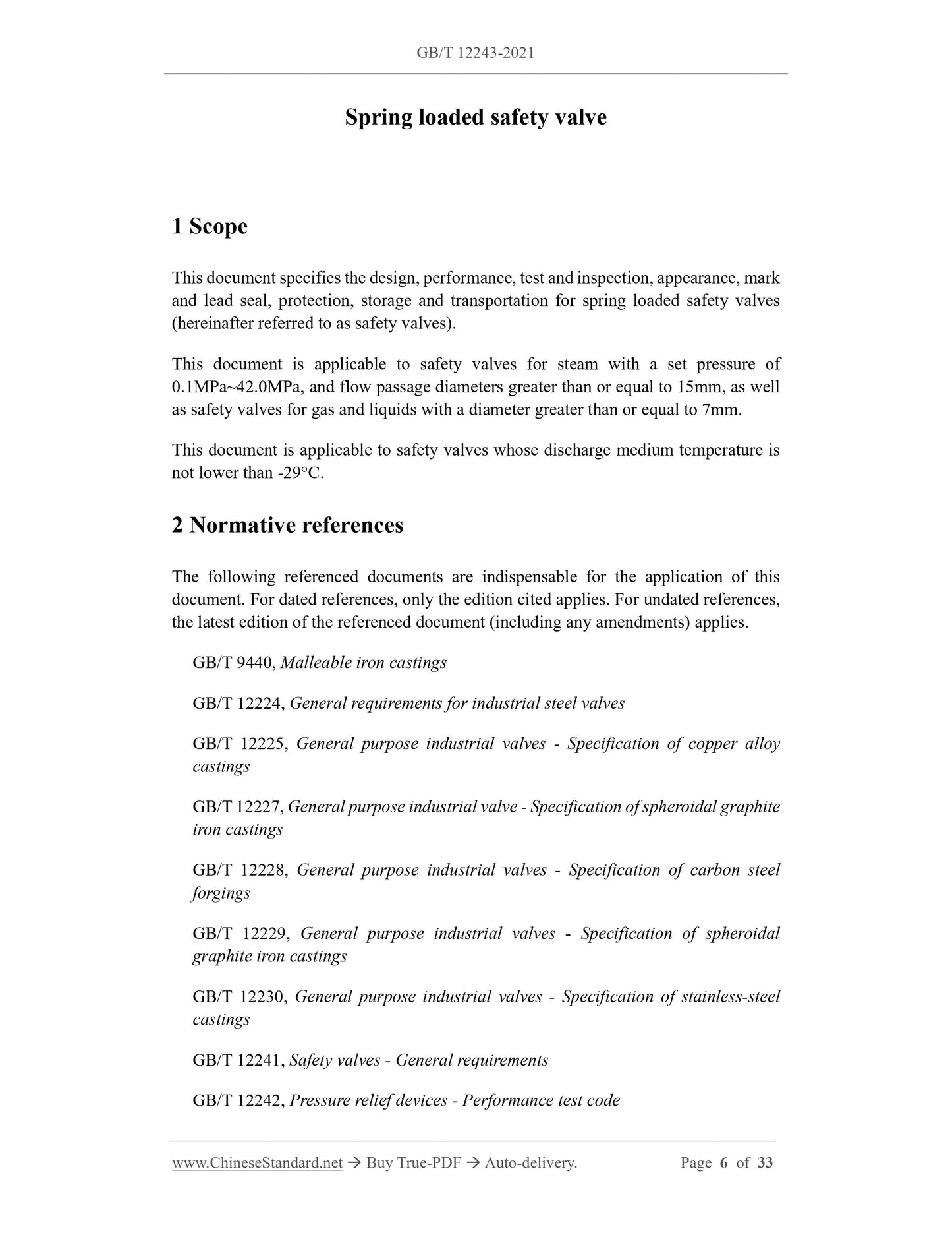
Spring direct load safety valve
1 Scope
This document specifies the design, performance, test and inspection, appearance, marking and lead of spring direct load safety valve (hereinafter referred to as safety valve)
Sealing, protection, storage and transportation.
This document is applicable to safety valves for steam with a set pressure of 0.1 MPa ~ 42.0 MPa and a flow channel diameter greater than or equal to 15 mm.
Or equal to 7mm gas and liquid safety valve.
This document applies to safety valves whose medium temperature is not lower than -29°C during discharge.
2 Normative references
The contents of the following documents constitute the indispensable clauses of this document through normative references in the text. Among them, dated quotations
Only the version corresponding to that date is applicable to this document; for undated reference documents, the latest version (including all amendments) is applicable to
This document.
GB/T 9440 malleable iron castings
GB/T 12224 General requirements for steel valves
GB/T 12225 General Valve Copper Alloy Casting Technical Conditions
GB/T 12227 Technical requirements for ductile iron castings for general purpose valves
GB/T 12228 Technical requirements for carbon steel forgings for general purpose valves
GB/T 12229 General Valve Carbon Steel Casting Technical Conditions
GB/T 12230 General Valve Stainless Steel Casting Technical Conditions
GB/T 12241 General requirements for safety valves
GB/T 12242 Specification for Performance Test of Pressure Relief Device
GB/T 23935 Cylindrical helical spring design calculation
JB/T 2203 spring direct load safety valve structure length
JB/T 5263 Power Station Valve Steel Casting Technical Conditions
JB/T 6439 Magnetic particle inspection of valve pressure parts
JB/T 6440-2008 Radiographic Inspection of Die Casting Steel Valves
JB/T 6902 valve liquid penetration test
JB/T 7367 Magnetic particle testing method for cylindrical spiral compression spring
NB/T 47013.2-2015 Non-destructive testing of pressure equipment Part 2.Radiographic testing
NB/T 47013.3-2015 Non-destructive testing of pressure equipment Part 3.Ultrasonic testing
NB/T 47013.5-2015 Non-destructive testing of pressure equipment Part 5.Penetration testing
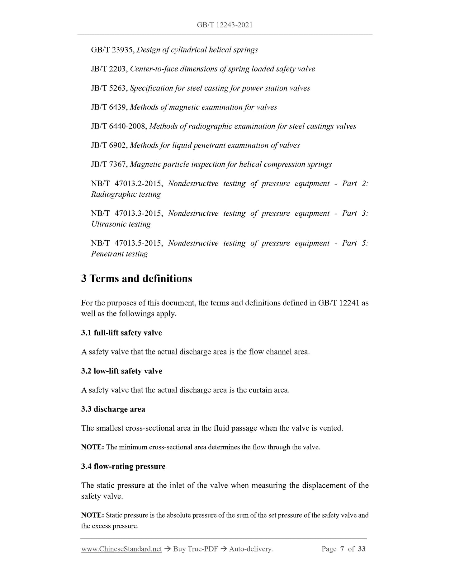
3 Terms and definitions
The following terms and definitions defined in GB/T 12241 apply to this document.
3.1
Full lift safety valve ful-liftsafetyvalve
The actual discharge area is the safety valve of the flow channel area.
3.2
Low-lift safety valve low-lift safety valve
A safety valve whose actual discharge area is the curtain area.
3.3
Dischargearea
The smallest cross-sectional area in the fluid passage when the valve is discharged.
Note. The minimum cross-sectional area determines the flow rate through the valve.
3.4
Rated flow pressure flow-rating pressure
The static pressure at the valve inlet when measuring the displacement of the safety valve.
Note. Static pressure is the absolute pressure of the sum of the set pressure of the safety valve and the excess pressure.
4 Design
4.1 General
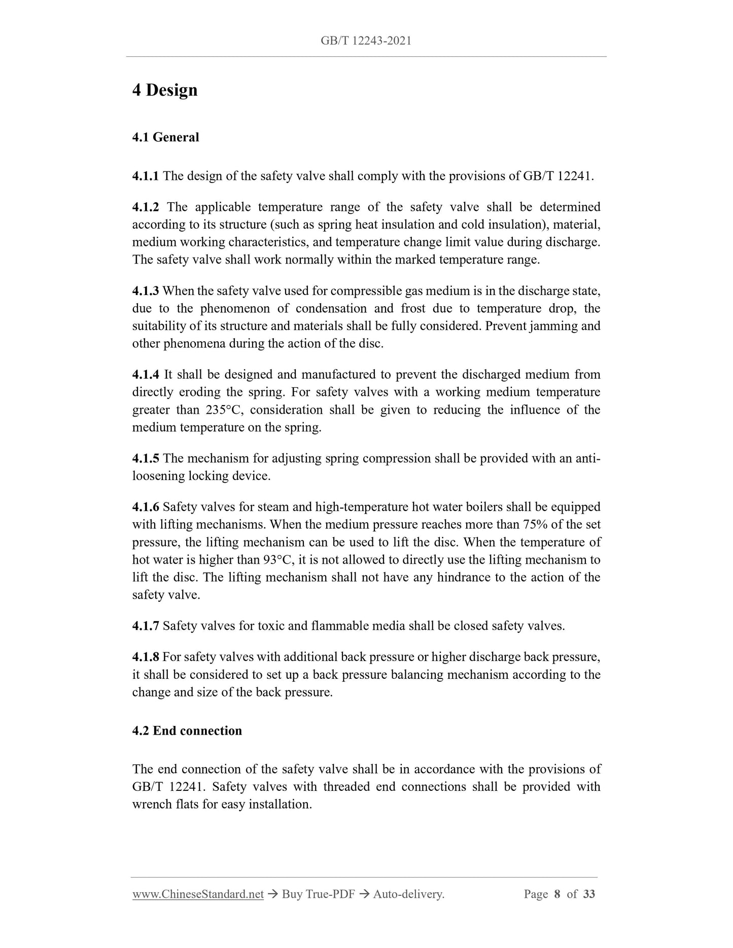
4.1.1 The design of the safety valve should meet the requirements of GB/T 12241.
4.1.2 The applicable temperature range of the safety valve should be based on its structure (such as spring insulation and cold insulation, etc.), materials, working characteristics of the medium, and the temperature at the time of discharge
Factors such as the change limit value are considered and determined. The safety valve should be able to work normally within the indicated temperature range.
4.1.3 When the safety valve used for compressible gas medium is in the discharge state, due to the temperature drop, it will cause condensation and frosting, etc., should be fully considered
Taking into account the suitability of its structure and materials, it can prevent the occurrence of jamming during the action of the disc.
4.1.4 The structure should be designed and manufactured to prevent the discharged medium from directly eroding the spring. Safety valve with working medium temperature greater than 235℃ should be tested
Consider reducing the influence of medium temperature on the spring.
4.1.5 The mechanism for adjusting the amount of spring compression should be provided with a locking device to prevent loosening.
4.1.6 The safety valve for steam and high-temperature hot water boilers should have a lifting mechanism. When the medium pressure reaches more than 75% of the set pressure,
The lifting mechanism can be used to lift the valve disc; when the hot water temperature is greater than 93°C, the lifting mechanism cannot be used directly to lift the valve disc. Lifting mechanism
There should be no hindrance to the action of the safety valve.
4.1.7 The safety valve for toxic and flammable media should be a closed safety valve.
4.1.8 For safety valves with additional back pressure or higher discharge back pressure, consider setting the back pressure level according to the change and size of the back pressure.
Balance agency.
4.2 End connection
The end connection of the safety valve should be in accordance with the provisions of GB/T 12241, and the safety valve connected with the threaded end should be provided with a wrench face for installation.
4.3 Limit deviation of structure length and perpendicularity
The structural length of the safety valve is in accordance with the provisions of JB/T 2203 or the requirements of the order contract, the structural length and the verticality of the end face of the inlet and outlet flanges
The limit deviation is as specified in Figure 1 and Table 1.
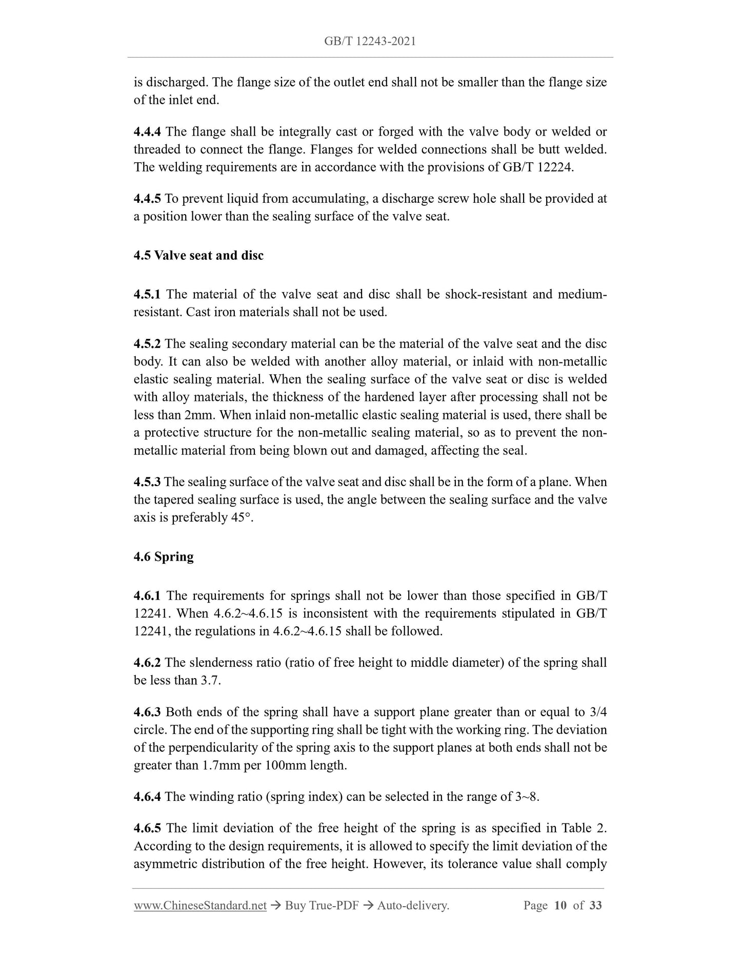
4.6.2 The slenderness ratio (the ratio of the free height to the pitch diameter) of the spring should be less than 3.7.
4.6.3 Both ends of the spring should have a support plane greater than or equal to 3/4 of the ring, the end of the support ring should be tight with the working ring, and the spring axis should be opposite to both ends.
The verticality of the supporting plane should not exceed 1.7mm per 100mm length.
4.6.4 The winding ratio (spring index) can be selected in the range of 3-8.
4.6.5 The limit deviation of the free height of the spring shall be in accordance with Table 2.According to design requirements, it is allowed to specify asymmetrically distributed poles for the free height.
Limit deviation, but its tolerance value should comply with the corresponding tolerance value calculated according to Table 2.
4.6.7 The pitch of the spring coils should be uniform. When the spring is compressed to the test load (that is, the maximum load allowed by the spring), the deformation is 80%
When, there should be no contact between the working circles.
4.6.8 The springs should be subjected to strong pressure treatment or heating and strong pressure treatment according to the design requirements, and all springs should be subjected to permanent deformation tests. Coming spring
After compressing the spring with a test load or compression and load for at least 3 times, measure its original free height; then apply the test load or compression and load compression to the spring.
Retract 3 times, and measure the final free height again after 10 minutes. The difference between the free height of the two measurements, that is, the amount of permanent deformation, should not exceed the original
0.5% of free height.
4.6.9 The deviation of spring stiffness should be ±7% (according to needs, the limit deviation of spring stiffness can be specified as asymmetrical distribution during design).
Take 10% (but not less than 2) of the springs of the same specification in the same heat treatment furnace and measure within the working load (or deformation) range specified in the design
The stiffness of the spring.
4.6.10 The spring surface of carbon steel and alloy steel materials should be treated with rust prevention.
4.6.11 The calculation of the spring and the test load of the spring shall be in accordance with the provisions of GB/T 23935.
4.6.12 The deformation of the spring under the minimum working load shall be calculated according to formula (1).
4.6.14 The spring deformation under the maximum working load shall be less than or equal to 80% of the spring deformation under the test load.
4.6.15 The deformation of the spring under the maximum working load should be less than or equal to 80% of the deformation when the spring coil is compressed.
4.7 Materials
4.7.1 Valve body material
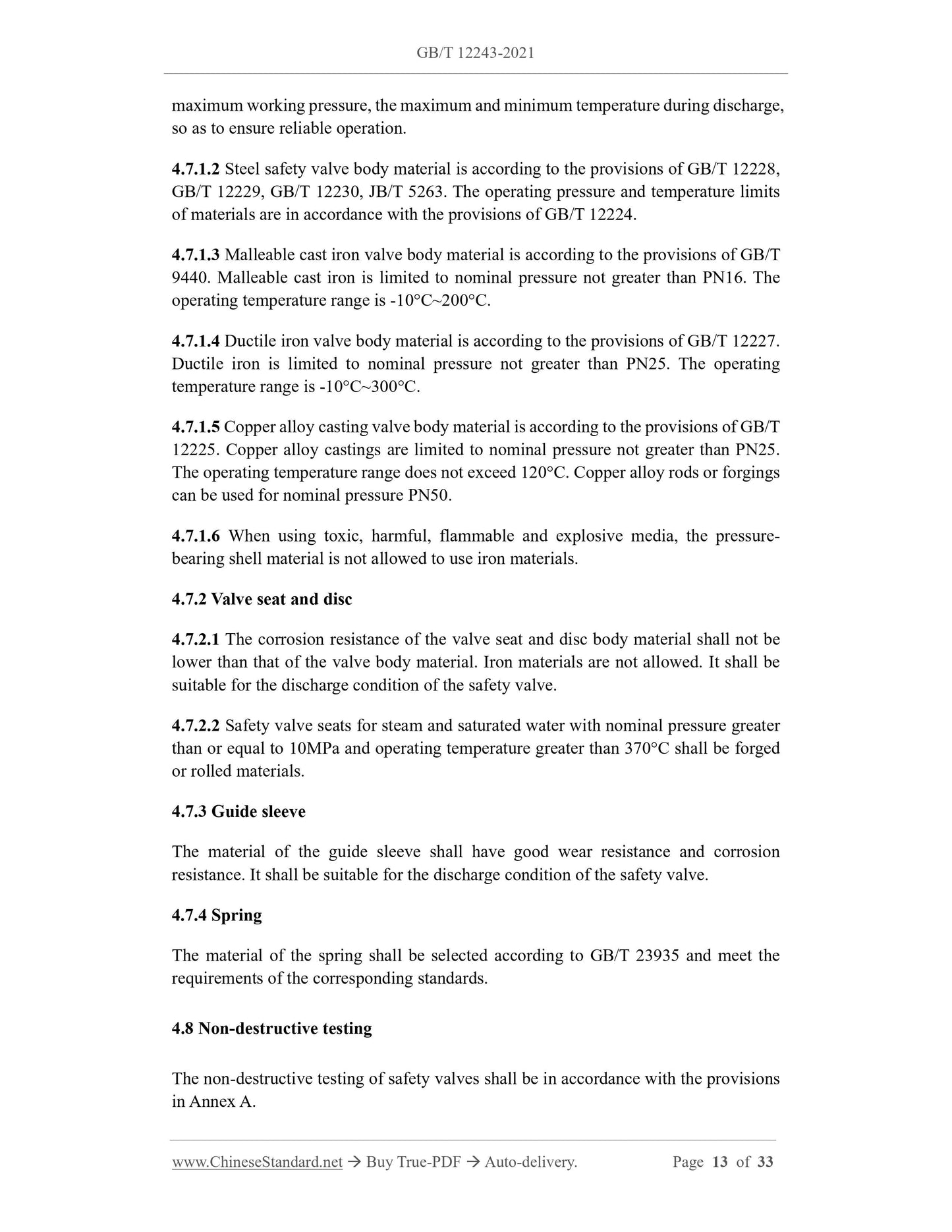
4.7.1.1 The valve body material should be adapted to the working medium, the highest working pressure, and the highest and lowest temperature during discharge to ensure reliable operation.
4.7.1.2 The material of the steel safety valve body is in accordance with the provisions of GB/T 12228, GB/T 12229, GB/T 12230, JB/T 5263,
The operating pressure and temperature limits are in accordance with the provisions of GB/T 12224.
4.7.1.3 The malleable cast iron valve body material is in accordance with the provisions of GB/T 9440, malleable cast iron is limited to the nominal pressure not greater than PN16, and the operating temperature
The range is -10℃~200℃.
4.7.1.4 The valve body material of ductile iron is in accordance with the provisions of GB/T 12227, and ductile iron is limited to the nominal pressure not greater than PN25, and the operating temperature
The range is -10℃~300℃.
4.7.1.5 The valve body material of copper alloy castings is in accordance with the provisions of GB/T 12225.The copper alloy castings are limited to the nominal pressure not greater than PN25.
The temperature range does not exceed 120°C. Copper alloy bars or forgings can be used for nominal pressure PN50.
4.7.1.6 When using toxic, hazardous, flammable and explosive media, the pressure-bearing shell material is not allowed to use iron materials.
4.7.2 Valve seat and disc
4.7.2.1 The corrosion resistance of the valve seat and disc body material should not be lower than that of the valve body material, and the use of iron materials is not allowed, and should be suitable for safety.
Valve discharge conditions.
4.7.2.2 The safety valve seat of steam and saturated water with nominal pressure greater than or equal to 10MPa and working temperature greater than 370℃ shall be forged
Or rolled materials.
4.7.3 Guide sleeve
The material of the guide sleeve should have good wear resistance and corrosion resistance, and should be suitable for safety valve discharge conditions.
4.7.4 Spring
The material of the spring should be selected according to GB/T 23935 and meet the requirements of the corresponding standard.
4.8 Non-destructive testing
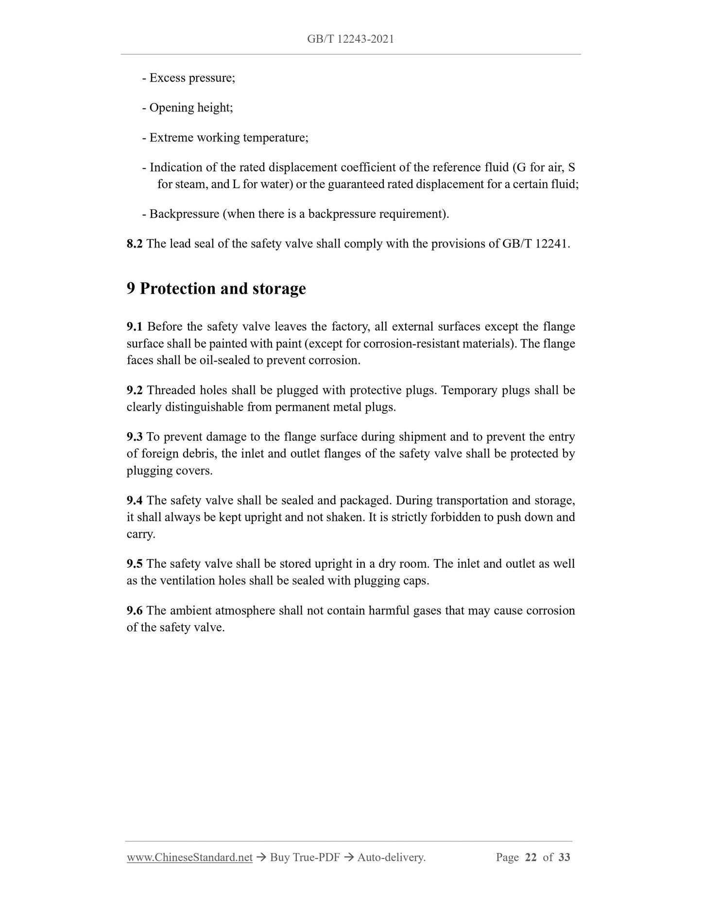
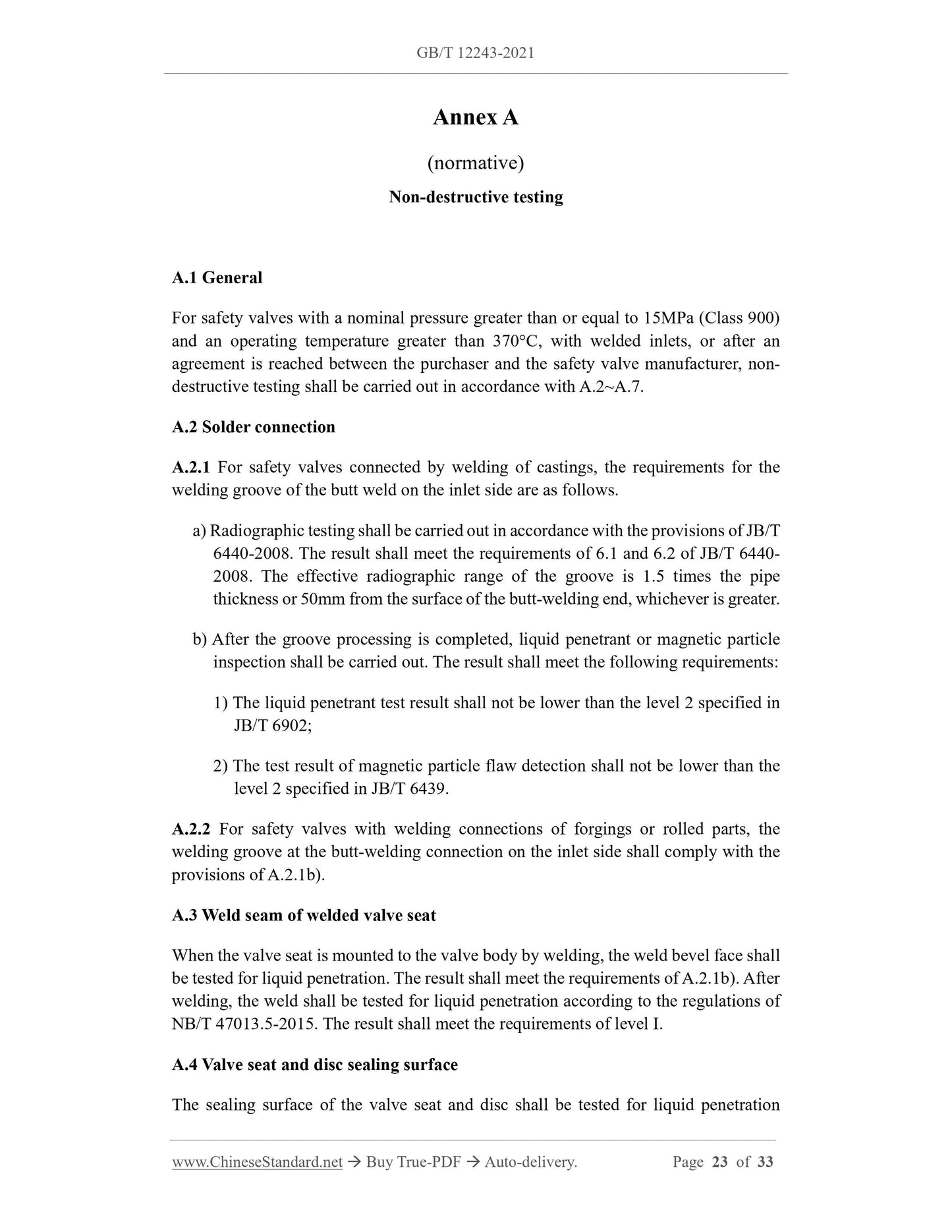
The non-destructive testing of the safety valve is in accordance with the provisions of Appendix A.
5 performance
5.1 Set pressure deviation
The set pressure deviation of the safety valve is in accordance with the regulations in Table 4 and Table 5.
6.2 General requirements
6.2.1 The factory test should be carried out before painting.
6.2.2 The test equipment, instruments and test procedures shall comply with the provisions of GB/T 12241 and GB/T 12242.When conducting shell strength test
The accuracy of the pressure gauge should not be lower than 1.6.
6.2.3 The safety requirements during the test shall comply with the provisions of GB/T 12241.
6.2.4 The set pressure test before leaving the factory should be carried out according to the set pressure specified in the order contract, and the number of tests should be no less than 2 times and adjusted to
This set pressure leaves the factory. If the order contract only stipulates the set pressure range, the factory should be adjusted according to the lower limit of the set pressure range.
6.3 Test medium
In the type test, the safety valve used for steam, the test medium is steam; the safety valve used for gas, the test medium is air or nitrogen; use
For liquid safety valves, the test medium is water.
The set pressure and sealing test medium of the safety valve for steam and liquid before leaving the factory are allowed to be replaced by air or nitrogen.
6.4 Test method
6.4.1 Shell strength
The shell strength test complies with the regulations of GB/T 12241.There should be no leakage and structural damage during the test.
6.4.2 Steam tightness test
For the tightness test of the steam safety valve, the set pressure should be verified before the tightness test. After reducing the inlet pressure, use the appropriate
Methods (such as drying with air, etc.) to completely drain the condensate that may exist in the body cavity. Increase the inlet pressure to the sealing test pressure and ensure at least
Hold for 3min. On a black background, visually check the tightness of the valve for at least 1 min, and there is no visual or auditory perceptible leakage.
6.4.3 Gas tightness test
6.4.3.1 The seat gas seal test of the closed bonnet safety valve for gas, the test arrangement is shown in Figure 2.Except for the leaking outlet pipe, install
6.4.4 Liquid tightness test
For the tightness test of safety valves for liquids, the...
View full details